
Introduction
A transistor is a type of semiconductor device that can be used to conduct and insulate electric current or voltage. A transistor basically acts as a switch and an amplifier. In simple words, we can say that a transistor is a miniature device that is used to control or regulate the flow of electronic signals.

The transistor is a simple component that you can use to build a lot of projects.
The transistor works like an electronic switch. It can turn a current ON and OFF. A simple way to think about it is to look at the transistor as a relay without any moving parts. A transistor is similar to a relay in the sense that you can use it to turn something ON and OFF.
But a transistor can also be turned partly on, which is useful for building amplifiers.
How Transistors Work (BJT)
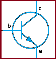
Let’s start with the classic NPN transistor. It’s a Bipolar Junction Transistor (BJT) and has three legs:
- Base (b)
- Collector (c)
- Emitter (e)
If you turn it ON, current can flow through it from the collector to the emitter. When it’s OFF, no current can flow.
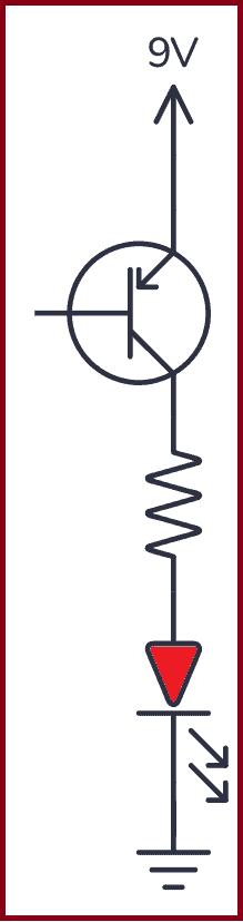
In the example circuit below, the transistor is OFF. That means no current can flow through it, so the Light-Emitting Diode (LED) is also off.

To turn the transistor ON, you need a voltage of about 0.7V between the base and the emitter.
If you had a 0.7V battery, you could have connected it between the base and emitter, and the transistor would have turned ON.
Since most of us don’t have a 0.7V battery, how do we turn on the transistor?
Easy! The base-to-emitter part of a transistor works like a diode. A diode has a forward voltage that it “grabs” from the available voltage. If you add a resistor in series, the rest of the voltage drops across the resistor.
So you’ll automatically get around 0.7V by adding a resistor.
This is the same principle you use to limit the current through an LED to make sure it doesn’t blow up.
If you also add a pushbutton, you can control the transistor, and thereby the LED, ON and OFF with a button:
Choosing Component Values
To choose the component values, there’s one more thing you need to know about how transistors work:
When a current flows from the base to the emitter, the transistor turns on so that a larger current can flow from the collector to the emitter.
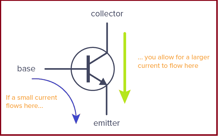
There is a connection between the sizes of the two currents. This is called the gain of the transistor.
For a general-purpose transistor, such as the BC547 or 2N3904, this could be around 100.
That means that if you have 0.1 mA flowing from the base to the emitter, you can have 10 mA (100 times more) flowing from collector to emitter.
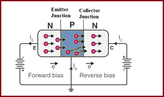
Operation of NPN Transistor
The emitter of the NPN device is made of n-type material; hence, the majority of carriers are electrons. When the base-emitter junction is forward-biased, the electrons will move from the n-type region towards the p-type region, and the minority carrier holes move towards the n-type region.
When they meet each other, they will combine, enabling a current to flow across the junction. When the junction is reverse-biased, the holes and electrons move away from the junction, and now, the depletion region forms between the two areas and no current will flow through it.
When a current flows between the base and emitter, the electrons will leave the emitter and flow into the base, as shown above. Normally, the electrons will combine when they reach the depletion region.
But the doping level in this region is very low, and the base is also very thin. This means that most of the electrons are able to travel across the region without recombining with holes. As a result, the electrons will drift towards the collector.
In this way, they are able to flow across what is effectively a reverse-biased junction, and the current flows in the collector circuit
What resistor value do you need for R1 to get 0.1mA flowing?
If the battery is 9V, and the base-to-emitter of the transistor grabs 0.7V, then there’s 8.3V left across the resistor.
You can use Ohm’s law to find the resistor value:
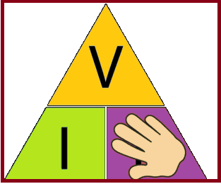
The Ohm’s Law triangle
So you need a resistor of 83 kΩ. That’s not a standard value, but 82 kΩ is, and it’s close enough.
R2 is there to limit the current to the LED. You can choose the value you would have chosen if you were to connect the LED and resistor directly to the 9V battery, without the transistor. For example, 1 kΩ should work fine.
Check out the video explanation I made on the transistor a few years back (forgive the old-school quality):
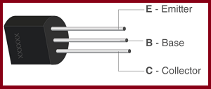
How To Choose a Transistor
The NPN transistor is the most common of the Bipolar Junction Transistors (BJT). But there is another one called a PNP transistor that works the same way, just that all the currents are in the opposite direction.
When choosing a transistor, the most important thing to keep in mind is how much current the transistor can support. This is called the Collector Current (IC).
Advantages of Transistor
- Lower cost and smaller in size.
- Smaller mechanical sensitivity.
- Low operating voltage.
- Extremely long life.
- No power consumption.
- Fast switching.
- Better efficiency circuits can be developed.
- Used to develop a single integrated circuit.
The advantage of a transistor is that you can use a small current or voltage to control a much larger current and voltage.
That’s super useful if you want to control things like motors, high-power LEDs, speakers, relays, and more from a Raspberry Pi/Arduino/microcontroller. The output pins from these boards can usually only provide a few milliamperes at 5V. So if you want to control your 110V outdoor patio lights, you can’t do it directly from the pin.
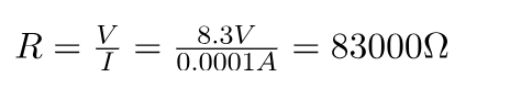
Instead, you could do it through a relay. But even the relay usually needs more current than the pin can provide. So you’d need a transistor to control the relay:
Connect left side of the resistor to an output pin (ex from Arduino) to control the relay
But transistors are also useful for simpler sensor circuits, like this light sensor circuit, the touch sensor circuit, or the H-Bridge circuit.
We use transistors in almost all circuits. It’s really the most important component in electronics.
The Transistor as an Amplifier
The transistor is also what makes amplifiers work. Instead of having just two states (ON/OFF) it can also be anywhere in between “fully on” and “fully off”.
That means a small signal with almost no energy can control a transistor to create a much stronger copy of that signal in the collector-emitter (or drain-source) part of the transistor. Thereby, the transistor can amplify small signals.
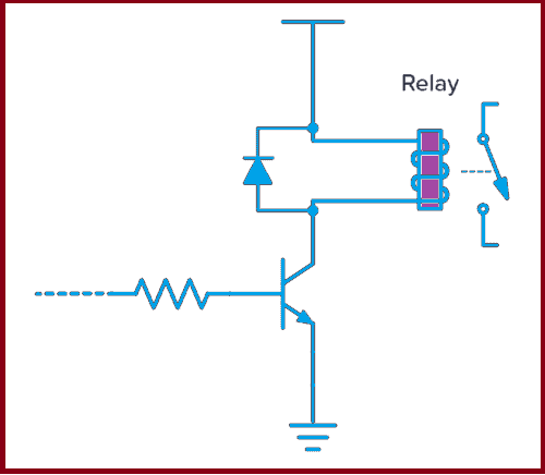
Below is a simple amplifier to drive a speaker. The higher the input voltage, the higher the current from base to emitter, and the higher the current through the speaker.
A varying input voltage makes the current in the speaker vary, which creates sound.
Common emitter amplifier
Normally, you’d add a couple of more resistors to bias the transistor. Otherwise you’ll get a lot of distortion
Types of Transistors
There are mainly two types of transistors, based on how they are used in a circuit.
Bipolar Junction Transistor (BJT)
The three terminals of BJT are the base, emitter and collector. A very small current flowing between the base and emitter can control a larger flow of current between the collector and emitter terminal.
Furthermore, there are two types of BJT, and they include:
- P-N-P Transistor: It is a type of BJT where one n-type material is introduced or placed between two p-type materials. In such a configuration, the device will control the flow of current. PNP transistor consists of 2 crystal diodes which are connected in series. The right side and left side of the diodes are known as the collector-base diode and emitter-base diode, respectively.
- N-P-N Transistor: In this transistor, we will find one p-type material that is present between two n-type materials. N-P-N transistor is basically used to amplify weak signals to strong signals. In an NPN transistor, the electrons move from the emitter to the collector region, resulting in the formation of current in the transistor. This transistor is widely used in the circuit.
PNP Transistor :
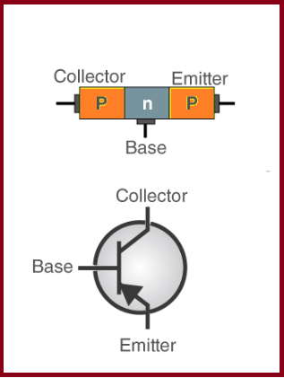
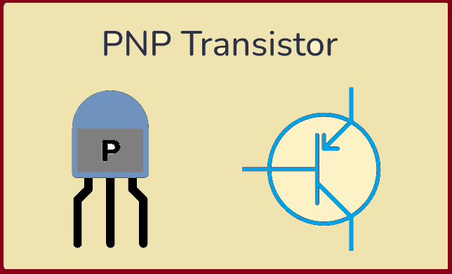
If you understand the NPN transistor, it will make it easier to understand the PNP transistor. They work pretty much in the same way, with one major difference: The currents in the PNP transistor flow in the opposite directions of the currents in the NPN transistor.
How PNP Transistors Work
The PNP transistor has the same leg names as the NPN:
- Base
- Emitter
- Collector
A PNP transistor will “turn on” when you have a small current running from emitter to base of the transistor. When I say “turn on”, I mean that the transistor will open up a channel between emitter and collector. And this channel can carry a much larger current.
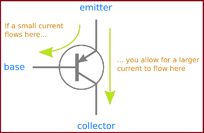
To get current running from emitter to base, you need a voltage difference of about 0.7V. Since the current goes from emitter to base, the base needs to be 0.7V lower than the emitter.
By setting the base voltage of a PNP transistor to 0.7V lower than the emitter, you “turn the transistor on” and allow for current to flow from emitter to collector.
Example: PNP Transistor Circuit
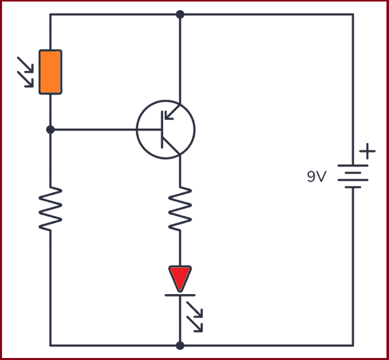
Let’s see how to create a simple PNP transistor circuit. With this circuit, you can turn on a light-emitting diode (LED) when it gets dark.
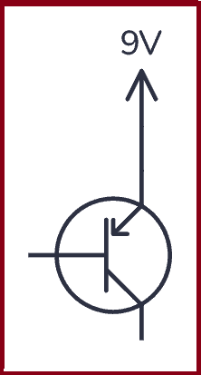
Step 1: The Emitter
First of all, to turn on the PNP transistor, you need the voltage on the base to be lower than the emitter. For a simple circuit like this, it’s common to connect the emitter to the plus from your power source. This way, you know what voltage you have on the emitter.
Step 2: What You Want To Control
When the transistor turns on, the current can flow from the emitter to the collector. So, let’s connect what we want to control: An LED. Since an LED should always have a resistor in series with it, let’s add a resistor too.
You can replace the LED and resistor with whatever you want to control.
Step 3: The Transistor Input
To turn on the LED, you need to turn on the transistor so that the channel from emitter to collector opens. To turn on the transistor you need to get the voltage on the base to be 0.7V lower than the emitter, which is 9V – 0.7V = 8.3V.
For example, you can now make the LED turn on when it gets dark by using a photoresistor and a standard resistor set up as a voltage divider.
The voltage on the base won’t behave exactly as the voltage divider formula tells you. This is because the transistor affects the voltage too.
But in general, when the photoresistor value is large (no light present) the voltage will be close to 8.3V and the transistor is on (which turns on the LED). When the value of the photoresistor is low (a lot of light present) the voltage will be close to 9V and turn off the transistor (which turns off the LED).
What Controls The Base Voltage?
You might wonder: “How did the photoresistor and resistor on the base magically create the correct voltage of 8.3V when it’s dark?”
It’s partly because the emitter and base makes up a diode. And a diode always try to get its diode voltage over itself. This particular diode has a diode-voltage of about 0.7V. And 8.3V is 0.7V less than 9V.
But, it’s also partly because the size of the photoresistor and resistor on the base sets up the voltage to be in the correct range.
How a MOSFET Transistor Works
Metal Oxide Silicon Field Effect Transistors commonly known as MOSFETs are electronic devices used to switch or amplify voltages in circuits. It is a voltage controlled device and is constructed by three terminals.
The MOSFET transistor is another very common type of transistor. It also has three pins:
- Gate (g)
- Source (s)
- Drain (d)
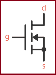
MOSFET symbol (N-channel)
A MOSFET works similar to the BJT transistor, but with one important difference:
In the BJT transistor, the current from base to emitter decides how much current can flow from collector to emitter.
In the MOSFET transistor, the voltage between gate and source decides how much current can flow from drain to source.
MOSFET Construction
The circuit of MOSFET is typically represented as follows:
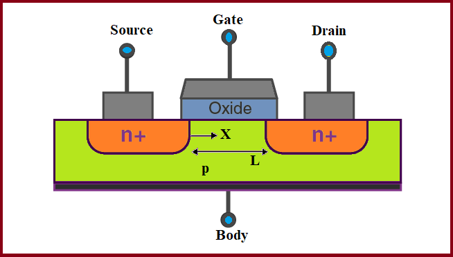
- The p-type semiconductor forms the base of the MOSFET.
- The two types of the base are highly doped with an n-type impurity which is marked as n+ in the diagram.
- From the heavily doped regions of the base, the terminals source and drain originate.
- The layer of the substrate is coated with a layer of silicon dioxide for insulation.
- A thin insulated metallic plate is kept on top of the silicon dioxide and it acts as a capacitor.
- The gate terminal is brought out from the thin metallic plate.
- A DC circuit is then formed by connecting a voltage source between these two n-type regions.
Example: How To Turn ON a MOSFET
Below is an example circuit for turning on a MOSFET.
To turn a MOSFET transistor on, you need a voltage between gate and source that is higher than the threshold voltage of your transistor. For example, the BS170 has a gate-source threshold voltage of 2.1V.
The threshold voltage of a MOSFET is actually the voltage where it turns off. So to turn the transistor properly on, you need a voltage a bit higher than that.
How much higher depends on how much current you’d like to have flowing. If you go a couple of volts above the threshold, that’s usually more than enough for low-current things like turning on an LED.
Note that even if you use a high enough voltage to have 1A current flowing, it doesn’t mean you’ll get 1A. It just means that you could have 1A flowing if you wanted to. But it’s whatever you connect to it that decides the actual current.
So you can go as high as you want, as long as you make sure you don’t go above the maximum gate-source voltage limit (which is 20V for the BS170).
In the example above, the gate is connected to 9V when you push the button. This turns the transistor on.
Choosing Component Values
The value of R1 isn’t crucial, but around 10 kΩ should work fine. Its purpose is to turn off the MOSFET (more about that below).
R2 sets the brightness of the LED. 1 kΩ should work fine for most LEDs.
Q1 could be almost any n-channel MOSFET, for example, BS170.
How To Turn OFF a MOSFET?
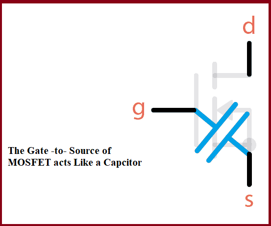
One important thing to learn about the MOSFET is that it also acts a bit like a capacitor. That is, the gate-source part. When you apply a voltage between gate and source, this voltage stays there until it’s discharged.
Without the resistor (R1) in the example above, the transistor wouldn’t turn off. With the resistor, there is a path for the gate-source capacitor to discharge so that the transistor turns off again.

How To Choose a MOSFET Transistor
The above example uses an N-channel MOSFET. P-channel MOSFETs work the same way, just that the current flows in the opposite direction, and the gate to source voltage must be negative to turn it on.
There are thousands of different MOSFETs to choose from. But if you want to build the example circuit above and want a specific recommendation, BS170 and IRF510 are two commons ones.
Two things to keep in mind when choosing a MOSFET is:
- The gate-to-source threshold voltage. You need a voltage higher than this to turn the transistor on.
- The Continuous Drain Current. This is the maximum amount of current that can flow through your transistor.
There are other important parameters to keep in mind, depending on what you’re making. But that’s out of the scope of this article. Keep the two parameters above in mind and you’ll have a good starting point.
MOSFET Gate Current
If you want to control a MOSFET from for example an Arduino or Raspberry Pi, there is another thing you need to keep in mind; the current that flows into the gate when you turn the transistor on.
As briefly mentioned above, the gate-to-source of a MOSFET acts as a capacitor.
That means once it’s charged, no more current flows through it. So when a MOSFET is on, there is no current flowing through the gate.
But when a MOSFET is being turned on, there is a current, just like when you charge a capacitor. For a small fraction of a second, there can be a lot of current flowing.
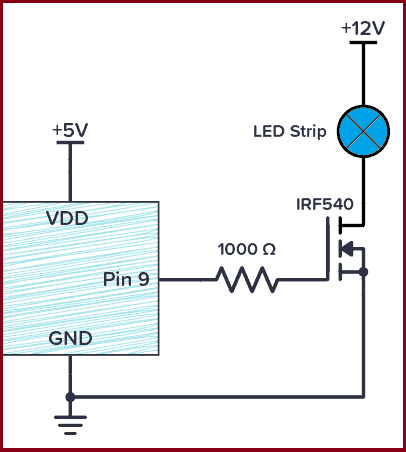
To protect your Arduino (or whatever you’re using) from too much current, you need to add a MOSFET gate resistor:
Often 1000 Ω is a good enough value for this. Use Ohm’s law to check for your specific case.
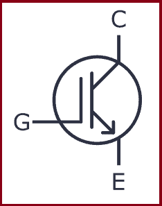
The Insulated Gate Bipolar Transistor (IGBT):
it is a device composed of semiconductor material and features three-terminals. Insulated gate bipolar transistors are mainly utilized for switching purposes. Insulated gate bipolar transistors consist of (P–N–P–N) four alternating layers that are controlled by a metal–oxide–semiconductor (MOS) gate structure
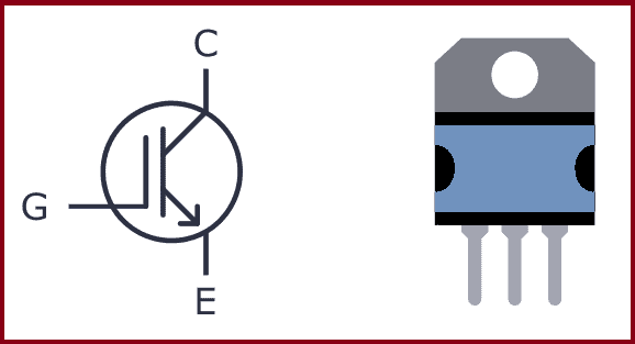
What is an IGBT?
An Insulated Gate Bipolar Transistor (IGBT) is a special type of transistor that can be useful in circuits where there is a lot of current that needs to be switched on and off. It’s a mix between a MOSFET and a BJT transistor.
It has three pins – Collector, Emitter, and Gate. As the name suggests the gate terminal is insulated from the rest, so no current flows into the gate, just like the MOSFET. When you turn it on, current flows between the collector and emitter pins.
The gate voltage controls how much current flows through the emitter-collector terminals. In other words, the input voltage controls the output current. So IGBT is a voltage-controlled transistor.
IGBT vs MOSFET
If you already know how MOSFETs work, you’re good to go, because IGBTs work the same way in a circuit. And the truth is that in most practical cases, you can think of the IGBT as a MOSFET.
The main difference is that the IGBT transistor can handle much higher currents and voltages than the MOSFET transistor.
Depending upon the device, an IGBT can handle currents as high as 500A and up. The gate voltage required to switch on an IGBT is usually around 4-8V.
Types of Insulated Gate Bipolar Transistors
There are two types of IGBT:
- Punch-through IGBT: Allows current to flow from collector to emitter only, not the other direction This type of IGBT is used in DC circuits and is also known as an asymmetricalIGBT.
- Non-punch-through IGBT: Allows for current to flow both ways – from collector to emitter – or from emitter to collector. This type of IGBT is used in AC circuits and it is also known as a symmetric IGBT.
So if you’re building an AC circuit, use the asymmetrical (punch-through) version. And if you’re building a DC circuit, use the symmetrical (non-punch-through) version.
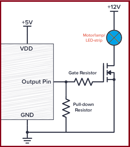
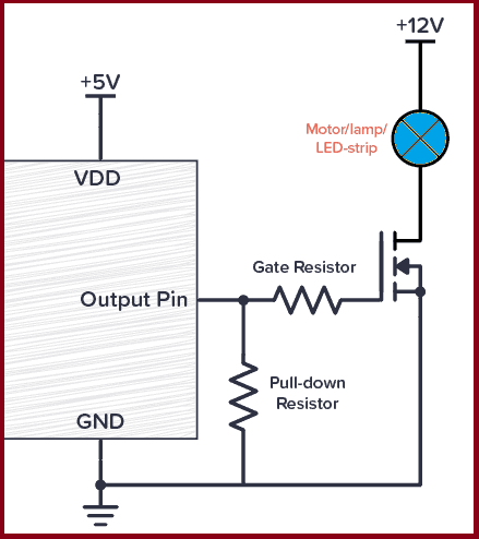
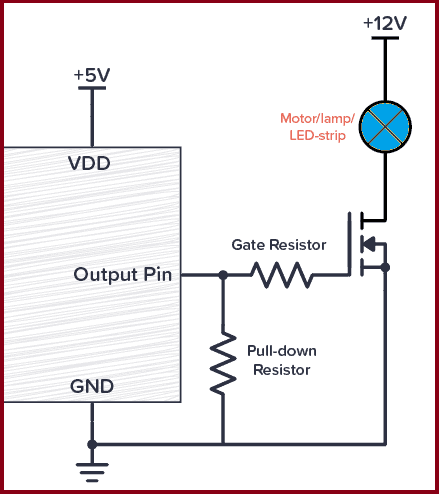
MOSFET Gate Resistor
Do you need a MOSFET gate resistor? What value should it be? And should it go before or after the pulldown resistor?
It will most likely work without a gate resistor, but adding one can prevent some potential problems. And 1000 Ω will most likely work. See the circuit diagram below for connecting your MOSFET gate resistor (the Pull-down resistor is optional):
Why Do You Need a Gate Resistor?
In how transistors work, we briefly touched upon that gate-to-source of a MOSFET acts as a capacitor.
And a capacitor works like this:
- When a capacitor is charging – current flows through it. A lot in the beginning, then less and less.
- When a capacitor is fully charged – no current flows through it.
When your MOSFET is turned on, its gate-source capacitor is fully charged. So there is no current flowing through the gate.
But when your MOSFET is being turned on, you’ll have a current that is charging this gate-source capacitor. So for a small fraction of a second, there can be a lot of current flowing.
To make sure this short burst of current isn’t too high for your Arduino/Raspberry Pi/microcontroller (or whatever you’ve connected it to) you need to add a resistor in series between the output pin and the MOSFET transistor’s gate:
Choosing A Resistor Value
Often 1000 Ω is a good enough value for this. But it depends on your circuit.
You can calculate the maximum current you get from a resistor by using Ohm’s law for current:
For example in the case of Arduino that has 5V on its output pins, 1000 Ω gives you a maximum current of 5 mA (and Arduino pins can handle up to 40 mA
If you want to switch the output on and off rapidly, keep in mind that the higher resistance you are using, the slower the MOSFET will turn on/off.
MOSFET Gate Resistor Placement
Are you using a pulldown resistor for your MOSFET? Then remember that if the gate resistor is placed to the left of the pulldown resistor, you get a voltage divider circuit that will reduce the voltage to the gate:
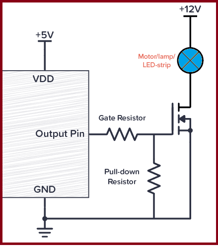
If you have chosen a gate resistor that is at least 100 times smaller than the pulldown resistor, then the reduction in voltage is so small that it doesn’t matter. But if they are a bit closer in value, the voltage on your gate will be lower than the pin voltage.
The solution? Switch places between the two so that the pulldown resistor is connected directly to the output pin:
MOSFET vs BJT
Main differences between MOSFET and BJT.
| MOSFET | BJT |
| There are two types of MOSFET and they are named: N-type or P-type | BJT is of two types and they are named as: PNP and NPN |
| MOSFET is a voltage-controlled device | BJT is a current-controlled device |
| The input resistance of MOSFET is high. | The input resistance of BJT is low. |
| Used in high current applications | Used in low current applications |
Phototransistor :
A phototransistor is an incredibly useful component for detecting light in electronics projects. You’ll often find them in remote-control receivers, pulse oximeters, and line-following robots.
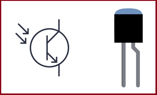
Phototransistor symbol and package
What Is a Phototransistor?
A phototransistor is a component that turns light into electricity. It is a type of transistor, just that it uses light instead of a base current to turn on and off. Its symbol looks like this:
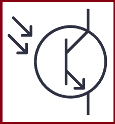
In a normal (BJT) transistor, the current from the base to the emitter controls the flow of current between the collector and emitter. In a phototransistor, light controls the flow of current between the collector and emitter.
Below you can see a simple circuit that you can use to convert light into a voltage to test a phototransistor:
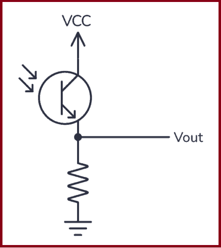
A simple circuit to convert light into voltage
There are two different types of phototransistors, NPN and PNP. NPN phototransistors are the most common and are used for low-power applications, such as proximity sensors or optical encoders. PNP phototransistors are less common and are used for applications such as smoke detectors or IR sensors.
How Phototransistors Work
A phototransistor has a base, collector, and emitter like a regular transistor, but instead of a pin to connect to the base, it has an internal photodiode that converts light into current that acts as the base current
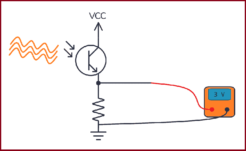
Simple setup to test a phototransistor
When light hits the photodiode, it produces a flow of electrons into the base of the transistor. This turns the transistor on so that current can flow from the collector to the emitter. The more light that hits the photodiode, the more electrons flow into the base, and the stronger the current becomes.
Phototransistors vs Photodiodes and Photoresistors
The main advantage of phototransistors over photodiodes and photoresistors is their high sensitivity to light. Because they have an in-built transistor that amplifies the current, they can detect very low levels of light.
They are also very fast, with response times of just a few nanoseconds, making them ideal for applications that require high-speed detection.
Phototransistors (and photodiodes) can be much smaller than a photoresistor, so you can fit hundreds into even small devices such as watches or calculators. And they consume less power.

Leave a comment