An Engineering manager having 8 year of experience in embedded and Internet of Things.
Some skills that i have:
Knowledge of maintenance and testing of Raspberry pi ,raspberry camera
Experience evaluating Python for Static code analysis, data flow analysis, metric analysis, and unit testing.
Extensive programming experience in embedded applications firmware
Experience working in as part of a team of Hardware developers.
Proficient in python ,Embedded c,Raspberry pi,Proteous,Ardiuno,micro controller,Node MCU,ESP32,Bluetooth,PCB designing and sensor,deep learning,opencv
After a long five-year wait, the Raspberry Pi 5 is finally on the horizon, and enthusiasts are eager to get their hands on this new iteration of the beloved single-board computer. Raspberry Pi, often referred to as RPI or RP, has consistently held its position as a go-to choice for affordable and versatile computing solutions. Since its debut back in 2012 with the original Model B sporting a single-core ARM processor and 256MB of RAM, it has seen significant evolution. Variants like the energy-efficient Model A and the performance-boosted Pi 2 with a quad-core processor followed. The Pi 3 introduced built-in Wi-Fi and Bluetooth, and in 2019, the Pi 4B brought substantial improvements, including up to 8GB of RAM and USB-C power. Now, as we anticipate the Raspberry Pi 5’s arrival, it’s the perfect time to compare it to the preceding Raspberry Pi 4 and explore the innovations it brings to the table.
Key features include:
2.4GHz quad-core 64-bit Arm Cortex-A76 CPU
VideoCore VII GPU, supporting OpenGL ES 3.1, Vulkan 1.2
Dual 4Kp60 HDMI® display output
4Kp60 HEVC decoder
Dual-band 802.11ac Wi-Fi®
Bluetooth 5.0 / Bluetooth Low Energy (BLE)
High-speed microSD card interface with SDR104 mode support
2 × USB 3.0 ports, supporting simultaneous 5Gbps operation
2 × USB 2.0 ports
Gigabit Ethernet, with PoE+ support (requires separate PoE+ HAT, coming soon)
2 × 4-lane MIPI camera/display transceivers
PCIe 2.0 x1 interface for fast peripherals
Raspberry Pi standard 40-pin GPIO header
Real-time clock
Power button
However, many Raspberry Pi enthusiasts and players will definitely have a question popping up in their minds: Should I buy it? Why should I choose it over other boards, for example, if I have got a Raspberry Pi 4, should I still buy a Raspberry Pi 5? Is it worth buying?
In this article, we will go through the comparison between Raspberry Pi 4 and Raspberry Pi 5. And let you know how the Raspberry Pi is upgraded.
Raspberry Pi 5 VS Raspberry Pi 4
Here below is an overview of the comparison between Raspberry Pi 5 and Raspberry Pi 4.
Performance
The Raspberry Pi 5 marks a significant leap in processor performance when compared to its predecessor, the Raspberry Pi 4. This improvement is driven by its 2.4GHz quad-core Arm Cortex-A76 CPU with 512KB L2 caches and a 2MB shared L3 cache. In contrast, the Raspberry Pi 4 features a quad-core Cortex-A72 CPU running at 1.5GHz with 1MB L2 cache and 32KB L1 cache. The Cortex-A76 architecture, combined with the higher clock speed, positions the Raspberry Pi 5 as a powerhouse, delivering superior performance for both single-threaded and multi-threaded computing tasks. Its enhanced processing capabilities translate to more power-efficient and faster experiences, especially in quantized machine-learning models. Additionally, the Raspberry Pi 5 consumes less power compared to the Raspberry Pi 4, making it an attractive choice for energy-conscious applications.
The Raspberry Pi 5 features LPDDR4X-4267 SDRAM, available in 4GB and 8GB SKUs, while the Raspberry Pi 4 is equipped with LPDDR4-3200 SDRAM, offered in 2GB, 4GB, and 8GB SKUs. The key differentiator here is the memory type and speed. LPDDR4X in the Raspberry Pi 5 is a more recent and faster memory technology compared to LPDDR4 in the Raspberry Pi 4. This means that the Raspberry Pi 5 has a significant advantage in memory bandwidth and data transfer rates, making it better suited for memory-intensive tasks, multitasking, and applications that require higher memory performance. Users seeking enhanced memory capabilities will find the Raspberry Pi 5’s LPDDR4X-4267 SDRAM a notable improvement over the Raspberry Pi 4’s LPDDR4-3200 SDRAM.
New platform, New chipset
Three new chips, each designed specifically for the Raspberry Pi 5 program, come together to deliver a step change in performance.
1.BCM2712
BCM2712 is a new 16-nanometer application processor (AP) from Broadcom, derived from the 28-nanometer BCM2711 AP which powers Raspberry Pi 4, with numerous architectural enhancements. At its heart is a quad-core 64-bit Arm Cortex-A76 processor, clocked at 2.4GHz, with 512KB per-core L2 caches, and a 2MB shared L3 cache. Cortex-A76 is three microarchitectural generations beyond Cortex-A72, and offers both more instructions per clock (IPC) and lower energy per instruction. The combination of a newer core, a higher clock speed, and a smaller process geometry yields a much faster Raspberry Pi, and one that consumes much less power for a given workload.
The new faster CPU is complemented by a newer, faster GPU: Broadcom’s VideoCore VII, developed in Cambridge, with fully open source Mesa drivers from Igalia. An updated VideoCore hardware video scaler (HVS) is capable of driving two simultaneous 4Kp60 HDMI displays, up from single 4Kp60 or dual 4Kp30 on Raspberry Pi 4. A 4Kp60 HEVC decoder and a new Image Sensor Pipeline (ISP), both developed at Raspberry Pi, round out the multimedia subsystem. To keep the system supplied with memory bandwidth,RPI5 have a 32-bit LPDDR4X SDRAM subsystem, running at 4267MT/s, up from an effective 2000MT/s on Raspberry Pi 4.
2.RP1
Previous Raspberry Pi generations were built on a monolithic AP architecture: while some peripheral functions were provided by an external device (the Via Labs VL805 USB controller and hub on Raspberry Pi 4, and the Microchip LAN951x and LAN7515 USB hub and Ethernet controller chips on earlier products), substantially all of the I/O functions were integrated into the AP itself.
Raspberry Pi 5, in contrast, is built on a disaggregated chiplet architecture. Here, only the major fast digital functions, the SD card interface (for board layout reasons), and the very fastest interfaces (SDRAM, HDMI, and PCI Express) are provided by the AP. All other I/O functions are offloaded to a separate I/O controller, implemented on an older, cheaper process node, and connected to the AP via PCI Express.
RP1 I/O controller for Raspberry Pi 5, designed by the same team at Raspberry Pi that delivered the RP2040 microcontroller, and implemented, like RP2040, on TSMC’s mature 40LP process. It provides two USB 3.0 and two USB 2.0 interfaces; a Gigabit Ethernet controller; two four-lane MIPI transceivers for camera and display; analogue video output; 3.3V general-purpose I/O (GPIO); and the usual collection of GPIO-multiplexed low-speed interfaces (UART, SPI, I2C, I2S, and PWM). A four-lane PCI Express 2.0 interface provides a 16Gb/s link back to BCM2712.
RP1 undergone substantial evolution over the years, as the projected requirements have changed: the C0 step used on Raspberry Pi 5 is the third major revision of the silicon. And while its interfaces differ in fine detail from those of BCM2711, they have been designed to be very similar from a functional perspective, ensuring a high degree of compatibility with earlier Raspberry Pi devices.
3.DA9091
BCM2712 and RP1 are supported by the third new component of the chipset, the Renesas DA9091 “Gilmour” power-management IC (PMIC). This integrates eight separate switch-mode power supplies to generate the various voltages required by the board, including a quad-phase core supply, capable of providing 20 amps of current to power the Cortex-A76 cores and other digital logic in BCM2712.
Like BCM2712, DA9091 is the product of a multi-year co-development effort. the Renesas team in Edinburgh produce a PMIC which is precisely tuned for RPI5. The Raspberry 5 have two frequently requested features: a real-time clock (RTC), which can be powered by an external super capacitor or a rechargeable lithium-manganese cell; and a PC-style power button, supporting hard and soft power-off and power-on events.
Two other elements of the chipset have been retained from Raspberry Pi 4. The Infineon CYW43455 combo chip provides dual-band 802.11ac Wi-Fi and Bluetooth 5.0 with Bluetooth Low-Energy (BLE); while the chip itself is unchanged, it is provided with a dedicated switched power supply rail for lower power consumption, and is connected to BCM2712 by an upgraded SDIO interface which supports DDR50 mode for higher potential throughput. As before, Ethernet connectivity is provided by a Broadcom BCM54213 Gigabit Ethernet PHY; this now sits at a jaunty 45-degree angle
Interfaces
The Raspberry Pi 5 represents a remarkable evolution in connectivity compared to its predecessor, the Raspberry Pi 4. Both models stand out with dual 4Kp60 display output capabilities over HDMI, offering an exceptional visual experience for both consumers and industrial users. Furthermore, both devices feature two USB 3.0 ports, providing the advantage of simultaneous 5Gbps operation.
A significant enhancement comes with the replacement of the dedicated two-lane 1Gbps MIPI camera and display interfaces present on earlier models. Instead, both the Raspberry Pi 4 and Raspberry Pi 5 now boast a pair of four-lane 1.5Gbps MIPI transceivers. This upgrade triples the total bandwidth, allowing for greater flexibility in supporting any combination of up to two cameras or displays. Notably, the Raspberry Pi 5’s unique feature is its two four-lane MIPI connectors that support both camera and display connections, utilizing a specialized 22-way, 0.5mm-pitch “mini” FPC format.
The Raspberry Pi 5 introduces a new feature not found in the Raspberry Pi 4: the M.2 HAT. This innovative accessory enables the connection of M.2-format PCIe and NVMe devices directly to the PCIe FPC connector on the Raspberry Pi 5. This enhancement offers users expanded storage options and the potential for higher-speed data transfer, making the Raspberry Pi 5 an even more versatile and powerful computing platform.
These impressive connectivity enhancements are made possible by the RP1 I/O controller chip, marking a significant milestone as it represents the first inclusion of Raspberry Pi-designed silicon in a flagship product. This underscores the Raspberry Pi 5’s dedication to providing advanced interfacing capabilities and expanding its potential for various applications.
27W USB-C Power Supply
Raspberry Pi 5 consumes significantly less power, and runs significantly cooler, than Raspberry Pi 4 when running an identical workload. However, the much higher performance ceiling means that for the most intensive workloads, and in particular for pathological “power virus” workloads, peak power consumption increases to around 12W, versus 8W for Raspberry Pi 4.
When using a standard 5V, 3A (15W) USB-C power adapter with Raspberry Pi 5, by default we must limit downstream USB current to 600mA to ensure that we have sufficient margin to support these workloads. This is lower than the 1.2A limit on Raspberry Pi 4, though generally still sufficient to drive mice, keyboards, and other low‑power peripherals.
Camera and display cables
The new, higher-density pinout of the MIPI connectors means that an adapter is required to connect our own cameras and displays, and third-party products, to Raspberry Pi 5.
To support existing camera and display owners, we are offering FPC camera and display cables, which convert from the higher-density format (now referred to as “mini”) to the older lower-density format (now referred to as “standard”). These cables are available in 200mm, 300mm, and 500mm lengths, priced at ₹100, ₹200, and ₹300 respectively.
RTC battery
Last, but very much not least, there is Panasonic lithium manganese rechargeable coin cell, with a pre-fitted two-pin JST plug and an adhesive mounting pad. This is priced at ₹500, and is suitable for powering the Raspberry Pi 5 real-time clock (RTC) when the main power supply is disconnected.
Cooling
The Active Cooler for the Raspberry Pi 5 offers an innovative cooling solution, especially beneficial for users who intend to push their Pi to its limits under sustained heavy loads without an enclosure. This cooler combines a substantial metal heatsink with a variable-speed blower, which is powered and controlled through the fan connector, effectively dissipating heat. It securely attaches to the Raspberry Pi 5 PCB using sprung pins that fit into dedicated mounting holes. The Raspberry Pi 5 released this cooling solution as an accessory, not built into the board itself.
Price
Indeed, the Raspberry Pi 5 offers more performance and additional features compared to the Raspberry Pi 4, with the 4GB RAM variant priced at ₹5000 and the 8GB version at ₹8000, just a ₹500 difference from the Raspberry Pi 4 counterparts. This minimal price gap makes upgrading to the Raspberry Pi 5 an attractive choice for users seeking enhanced capabilities and versatility without a significant budgetary increase.
Conclusion
In a nutshell, the Raspberry Pi 5 offers a significant performance boost, with CPU speeds 2-3 times faster than its predecessor, the Raspberry Pi 4. This improvement, coupled with enhanced GPU capabilities, makes it a powerhouse for various computing tasks.
Despite its substantial performance gains, the Raspberry Pi 5 remains budget-friendly, with prices just slightly higher than the Raspberry Pi 4. This cost-effectiveness, combined with innovative features like the Active Cooler for efficient cooling and improved connectivity options, solidifies its position as a top choice for hobbyists and enthusiasts looking for a versatile and affordable single-board computer
Serial peripheral interface (SPI) is one of the most widely used interfaces between microcontroller and peripheral ICs such as sensors, ADCs, DACs, shift registers, SRAM, and others. This article provides a brief description of the SPI interface followed by an introduction to Analog Devices’ SPI enabled switches and muxes, and how they help reduce the number of digital GPIOs in system board design.
SPI is a synchronous, full duplex main-subnode-based interface. The data from the main or the subnode is synchronized on the rising or falling clock edge. Both main and subnode can transmit data at the same time. The SPI interface can be either 3-wire or 4-wire. This article focuses on the popular 4-wire SPI interface.
Interface
Figure 1. SPI configuration with main and a subnode.
4-wire SPI devices have four signals:
Clock (SPI CLK, SCLK)
Chip select (CS)
main out, subnode in (MOSI)
main in, subnode out (MISO)
The device that generates the clock signal is called the main. Data transmitted between the main and the subnode is synchronized to the clock generated by the main. SPI devices support much higher clock frequencies compared to I2C interfaces. Users should consult the product data sheet for the clock frequency specification of the SPI interface.
SPI interfaces can have only one main and can have one or multiple subnodes. Figure 1 shows the SPI connection between the main and the subnode.
The chip select signal from the main is used to select the subnode. This is normally an active low signal and is pulled high to disconnect the subnode from the SPI bus. When multiple subnodes are used, an individual chip select signal for each subnode is required from the main. In this article, the chip select signal is always an active low signal.
MOSI and MISO are the data lines. MOSI transmits data from the main to the subnode and MISO transmits data from the subnode to the main.
Data Transmission
To begin SPI communication, the main must send the clock signal and select the subnode by enabling the CS signal. Usually chip select is an active low signal; hence, the main must send a logic 0 on this signal to select the subnode. SPI is a full-duplex interface; both main and subnode can send data at the same time via the MOSI and MISO lines respectively. During SPI communication, the data is simultaneously transmitted (shifted out serially onto the MOSI/SDO bus) and received (the data on the bus (MISO/SDI) is sampled or read in). The serial clock edge synchronizes the shifting and sampling of the data. The SPI interface provides the user with flexibility to select the rising or falling edge of the clock to sample and/or shift the data. Please refer to the device data sheet to determine the number of data bits transmitted using the SPI interface.
Clock Polarity and Clock Phase
In SPI, the main can select the clock polarity and clock phase. The CPOL bit sets the polarity of the clock signal during the idle state. The idle state is defined as the period when CS is high and transitioning to low at the start of the transmission and when CS is low and transitioning to high at the end of the transmission. The CPHA bit selects the clock phase. Depending on the CPHA bit, the rising or falling clock edge is used to sample and/or shift the data. The main must select the clock polarity and clock phase, as per the requirement of the subnode. Depending on the CPOL and CPHA bit selection, four SPI modes are available. Table 1 shows the four SPI modes.
Table 1. SPI Modes with CPOL and CPHA
SPI Mode
CPOL
CPHA
Clock Polarity in Idle State
Clock Phase Used to Sample and/or Shift the Data
0
0
0
Logic low
Data sampled on rising edge and shifted out on the falling edge
1
0
1
Logic low
Data sampled on the falling edge and shifted out on the rising edge
2
1
0
Logic high
Data sampled on the rising edge and shifted out on the falling edge
3
1
1
Logic high
Data sampled on the falling edge and shifted out on the rising edge
In these examples, the data is shown on the MOSI and MISO line. The start and end of transmission is indicated by the dotted green line, the sampling edge is indicated in orange, and the shifting edge is indicated in blue. Please note these figures are for illustration purpose only. For successful SPI communications, users must refer to the product data sheet and ensure that the timing specifications for the part are met.
Figure 2. SPI Mode 0, CPOL = 0, CPHA = 0: CLK idle state = low, data sampled on rising edge and shifted on falling edge.
Figure 3 shows the timing diagram for SPI Mode 1. In this mode, clock polarity is 0, which indicates that the idle state of the clock signal is low. The clock phase in this mode is 1, which indicates that the data is sampled on the falling edge (shown by the orange dotted line) and the data is shifted on the rising edge (shown by the dotted blue line) of the clock signal.
Figure 3. SPI Mode 1, CPOL = 0, CPHA = 1: CLK idle state = low, data sampled on the falling edge and shifted on the rising edge.
Figure 4 shows the timing diagram for SPI Mode 3. In this mode, the clock polarity is 1, which indicates that the idle state of the clock signal is high. The clock phase in this mode is 1, which indicates that the data is sampled on the falling edge (shown by the orange dotted line) and the data is shifted on the rising edge (shown by the dotted blue line) of the clock signal.
Figure 4. SPI Mode 3, CPOL = 1, CPHA = 1: CLK idle state = high, data sampled on the falling edge and shifted on the rising edge.
Figure 5 shows the timing diagram for SPI Mode 2. In this mode, the clock polarity is 1, which indicates that the idle state of the clock signal is high. The clock phase in this mode is 0, which indicates that the data is sampled on the rising edge (shown by the orange dotted line) and the data is shifted on the falling edge (shown by the dotted blue line) of the clock signal.
Figure 5. SPI Mode 2, CPOL = 1, CPHA = 0: CLK idle state = high, data sampled on the rising edge and shifted on the falling edge.
Multi-Subnode Configuration
Multiple subnodes can be used with a single SPI main. The subnodes can be connected in regular mode or daisy-chain mode.
Regular SPI Mode:
Figure 6. Multi-subnode SPI configuration.
In regular mode, an individual chip select for each subnode is required from the main. Once the chip select signal is enabled (pulled low) by the main, the clock and data on the MOSI/MISO lines are available for the selected subnode. If multiple chip select signals are enabled, the data on the MISO line is corrupted, as there is no way for the main to identify which subnode is transmitting the data.
As can be seen from Figure 6, as the number of subnodes increases, the number of chip select lines from the main increases. This can quickly add to the number of inputs and outputs needed from the main and limit the number of subnodes that can be used. There are different techniques that can be used to increase the number of subnodes in regular mode; for example, using a mux to generate a chip select signal.
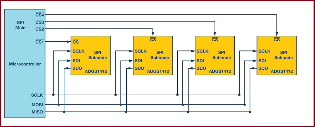
In daisy-chain mode, the subnodes are configured such that the chip select signal for all subnodes is tied together and data propagates from one subnode to the next. In this configuration, all subnodes receive the same SPI clock at the same time. The data from the main is directly connected to the first subnode and that subnode provides data to the next subnode and so on.
In this method, as data is propagated from one subnode to the next, the number of clock cycles required to transmit data is proportional to the subnode position in the daisy chain. For example, in Figure 7, in an 8-bit system, 24 clock pulses are required for the data to be available on the 3rd subnode, compared to only eight clock pulses in regular SPI mode. Figure 8 shows the clock cycles and data propagating through the daisy chain. Daisy-chain mode is not necessarily supported by all SPI devices. Please refer to the product data sheet to confirm if daisy chain is available.
Figure 8. Daisy-chain configuration: data propagation.
Analog Devices SPI Enabled Switches and Muxes
The newest generation of ADI SPI enabled switches offer significant space saving without compromise to the precision switch performance. This section of the article discusses a case study of how SPI enabled switches or muxes can significantly simplify the system-level design and reduce the number of GPIOs required.
The ADG1412 is a quad, single-pole, single-throw (SPST) switch, which requires four GPIOs connected to the control input of each switch. Figure 9 shows the connection between the microcontroller and one ADG1412.
Figure 9. Microcontroller GPIO as control signals for the switch.
As the number of switches on the board increases, the number of required GPIOs increases significantly. For example, when designing a test instrumentation system and a large number of switches are used to increase the number of channels in the system. In a 4 × 4 cross-point matrix configuration, four ADG1412s are used. This system would require 16 GPIOs, limiting the available GPIOs in a standard microcontroller. Figure 10 shows the connection of four ADG1412s using the 16 GPIOs of the microcontroller.
Figure 10. In a multi-subnode configuration, the number of GPIOs needed increases tremendously.
One approach to reduce the number of GPIOs is to use a serial-to-parallel converter, as shown in Figure 11. This device outputs parallel signals that can be connected to the switch control inputs and the device can be configured by serial interface SPI. The drawback of this method is an increase in the bill of material by introducing an additional component.
Figure 11. Multi-subnode switches using a serial-to-parallel converter.
An alternative method is to use SPI controlled switches. This method provides the benefit of reducing the number of GPIOs required and also eliminates the overhead of additional serial-to-parallel converter. As shown in Figure 12, instead of 16 microcontroller GPIOS, only seven microcontroller GPIOs are needed to provide the SPI signals to the four ADGS1412s.
Figure 12. SPI enabled switches save up microcontroller GPIOs.
The switches can be configured in daisy-chain configuration to further optimize the GPIO count. In daisy-chain configuration, irrespective of the number of switches used in the system, only four GPIOs are used from the main (microcontroller).
Figure 13. SPI enabled switches configured in a daisy chain to further optimize the GPIOs.
Difference between UART, I2c, and SPI
Protocol
Complexity
Speed
# of Devices
# of Wries
Duplex
No. of master and slave
UART
Simple
Slowest
Up to 2 devices
1
Full Duplex
Single to Single
I2C
Easy to chain multiple devices
Faster than UART
Up to 127, but gets complex
2
Half Duplex
Multiple slaves and master
SPI
Complex as device increases
Fastest
Many, but gets complex
4
Full Duplex
1 master, multiple slaves
Advantages of using SPI
Support full-duplex communication, which means data can be transmitted and received at the same time.
Better signal integrity, supporting high-speed applications.
The hardware connection is simple, only four signal lines are needed (some applications can be reduced to three).
No transceiver required.
The slave device does not need to address.
Disadvantages of using SPI
Short transmission distance.
There is no flow control specified, and no acknowledgement mechanism confirms whether data is received, unlike I2C.
More Pin ports are occupied, the practical limit to the number of devices.
No form of error check unlike in UART (using parity bit).
Interrupt operation can only be done through additional signal lines.
Raspberry Pi Pico, a brand new exciting Microcontroller board based on RP2040 Microcontroller from the Raspberry Pi Foundation. The Raspberry Pi Pico is a low-cost Arm-based microcontroller that we can program using C/C++ and MicroPython.
Over the years Raspberry Pi boards have become a must tool for students, hobbyists,s or Industrialists. But when it comes to cost, the Raspberry Pi Board is overtaken by Arduino, ESP32, STM32, or other AVR, ARM, and PIC Microcontrollers. The Raspberry Pi computer costs around ₹ 3000-₹4000 whereas the other microcontrollers barely cost 300-400₹ only. This is the reason why Raspberry Pi Foundation released their low-cost powerful competitive Raspberry Pi Pico Board with RP2040, a Dual Core ARM Cortex-M0+ Microcontroller.
The tutorial covers the RP2040 Microcontroller, its features & specifications. We will also learn about the Raspberry Pi Pico Board, its layout, and specifications. The detailed guide of Raspberry Pi Pico Pins like ADC pins, I2C Pins, SPI Pins, UART, etc can help you to interface any sensors or module with this powerful board.
Since it’s a Raspberry Pi Pico getting started tutorial, so we will only program the device using Micropython. For that, you can either use Thonny IDE or you can also go with uPyCraft IDE. In some other tutorials, we will learn how to program Raspberry Pi Pico with C/C++. Even the Arduino IDE will support Raspberry Pie Pico in the future as it is in the development phase now.
What is the RP2040 Microcontroller?
Earlier all the Raspberry Pi boards like Raspberry Pi 3 or 4 or Raspberry Pi Zero featured Broadcom Processors like BCM2835, BCM2836, BCM2711, etc. The RP2040 chip was announced on 21st January 2021 and is the first processor designed by the Raspberry Pi Foundation.
The RP2040 is a 32-bit dual ARM Cortex-M0+ microcontroller integrated circuit released simultaneously as part of the Raspberry Pi Pico board. The processor is a low-cost microcontroller and costs around US$4. The chip is 40nm silicon in a 7×7 mm QFN-56 package.
The RP2040 contains two ARM Cortex-M0+ cores clocked at 133 MHz together with 264 KB of RAM. The Program memory is external and supports up to 16 MB. The device has everything you expect from a modern microcontroller like UARTS, SPI, and I2C ports, and there are timers, PWM, DMA, and a 12-bit analog-to-digital converter (ADC).
Meaning of RP2040
The name RP2040 has an exciting meaning explained below. 1. RP means: Raspberry Pi 2. Number 2 means: Processor Cores as a dual-core microcontroller. So, the value is 2. 3. Number 0 means: Type of Processor Core as it is ARM Cortex-M0+. So, the value is 0. 4. Number 4 means: Represents On-chip RAM. RP2040 has 264 KB of RAM. The formula to get 4 values is floor (log2 (ram / 16k)). So, the value is 4. 5. Number 0 means: Represents On-chip Flash. As there is no on-chip flash, the value is 0.
RP2040 Key features:
1. 133MHz dual ARM Cortex-M0+ cores 2. 264kB SRAM in six independent banks 3. Support for up to 16MB of off-chip Flash memory via a dedicated QSPI bus 4. DMA controller 5. Fully-connected AHB crossbar 6. Interpolator and integer divider peripherals 7. On-chip programmable LDO(Low-dropout_regulator) to generate core voltage 8. 2 on-chip PLLs to generate USB and core clocks 9. 30 GPIO pins, 4 of which can be used as analog inputs
Introduction to Raspberry Pi Pico
The Raspberry Pi Pico is the first microcontroller board based on the RP2040. It looks a lot like other microcontroller boards with the MCU in the center, a micro-USB connector on one end, and a row of contacts along each side. A 3-pin debug connector is available at the other end of the board.
The Raspberry Pi Pico measures 51 by 21 mm, which is the exact same size as an ESP32 Pico Kit & slightly larger than an Arduino Nano or Micro. The Pico comes with 2 MB of QSPI Flash memory and 25 of the 30 GPIO pins of the RP2040 have been brought out on the extension connectors. The board is breadboard friendly and fits perfectly on a breadboard.
Features of Raspberry Pi Pico
Following are the features of the Raspberry Pi Pico Board. 1. Based on RP2040 Microcontroller 2. 2 MB of SPI Flash Memory 3. Type B Micro-USB port for power & programming 4. 40 DIP style IO Pins 5. 3-pin ARM Serial Wire Debug (SWD) interface 6. 12 MHz Crystal oscillator 7. Boot Selection Button 8. Programmable LED connected to GPIO 25 9. 3.3V Fixed Output Buck-Boost SMPS Converter
Raspberry Pi Pico Pinout
There are 40 pins on the Raspberry Pi Pico. Out of those 40 pins, 26 pins are Input-Output (IO Pins). All those 14 pins are analog, digital, and other Serial Pins. There are 14 power and system-related pins. The remaining 3 more pins are used for SWD Debugging.
There are two I2C peripherals available, I2C0 and I2C1. Similarly, there are two SPI peripherals, SPI0 and SPI1The number of UART Pins is also two, UART0 and UART1. You can assign any of these to the pins on which they are available.
Before you start using Raspberry Pi Pico, you have to solder 40-pin male headers, 20 on each side of the board.
RP2040 is an ARM Cortex-M0+ dual-core microcontroller. That means you have two separate processors inside the package that can execute your code parallelly. It is like having two microcontrollers for the price of one. Both cores run at 133 MHz and they could be even overclocked! Cortex-M0+ is a series of ARM microcontrollers that are optimized for power consumption. Like all ARM Cortex microcontrollers, RP2040 also has a 32-bit core, which means it can execute complex 32-bit instructions in every instance. It is also a RISC processor which can execute a single instruction in just 1 clock cycle.
Let’s see a comparison between RP2040 and the popular ATmega328P, which is used in the Arduino Uno board. Only a few features are compared.
Property
RP2040
ATmega328P
Core Type
ARM Cortex-M0+
8-bit AVR
Instruction Type
RISC
RISC
Instruction Size
32-bit
8-bit
Core Count
2
1
Maximum Clockspeed
133 MHz
20 MHz
SRAM
264 KB
2 KB
Flash Size
16 MB
32 KB
GPIO Count
30
23
ADC Resolution
12 bit
10 bit
PWM
All GPIO pins
Limited GPIO pins
Interrupt
All GPIO pins
2 GPIO pins
UART
2
1
SPI
2
1
I2C
2
1
USB
Yes
No
Price
₹200
₹500
Firmware Lock Protection
No
Yes
Working Voltage
1.8 to 3.3V
1.8 to 5.5V
Comparison between RP2040 and ATmega328P
There are more differences between the two and features that make the RP2040 a really good choice for your projects and products. RP2040 was designed by Raspberry Pi’s own engineers and uses a 40 nm node for fabrication. It is available in a 56-pin QFN package with a 7 x 7 mm size. This is one of the caveats for using RP2040. It can be a little difficult to hand-solder it. The another one is having no firmware lock protection since the flash memory has to be off-chip. So you can not protect your firmware from being copied easily.
Specifications
Dual ARM Cortex-M0+ @ 133MHz
On-chip PLL allows variable core frequency
264kByte high-performance SRAM in six independent banks
Support for up to 16MB of off-chip Flash memory via dedicated QSPI bus with eXecute In Place (XIP)
DMA controller
Fully-connected AHB crossbar
Interpolator and integer divider peripherals
On-chip programmable LDO to generate the core voltage
2 on-chip PLLs to generate USB and core clocks
30 multi-function General Purpose IO (4 can be used for ADC)
1.8-3.3V IO Voltage (NOTE: Pico IO voltage is fixed at 3.3V)
12-bit 500ksps Analogue to Digital Converter (ADC)
Peripherals
2 UARTs
2 SPI controllers
2 I2C controllers
16 PWM channels
USB 1.1 controller and PHY, with host and device support
8 PIO state machines
2 × Programmable IO (PIO) blocks, 8 state machines total
Flexible, user-programmable high-speed IO
Can emulate interfaces such as SD Card and VGA
QFN-56 7x7mm package
Block Diagram
As you can see, there is no flash memory embedded in the chip. We have to add an external Flash memory to store all the programs. A dedicated set of QSPI pins are provided for this so that you don’t need to spare any GPIOs for the purpose. There are dedicated pins for SWD (Serial Wire Debug), USB, and crystal oscillator.
Pinout
RP2040 pinout
Programming Raspberry Pi Pico
The Pi Pico can be programmed using C/C++ or Python, among other languages. Pico is adaptable to a vast range of applications and skill levels, and getting started is as easy as dragging and dropping a file. If you are working with C, then it is recommended to use a Linux-based system like a Raspberry Pi Computer as it is easy to download the SDK and write C Programs in Linux.
But I will recommend using MicroPython to program the Raspberry Pi Pico Board. MicroPython is a Python Language Interpreter that is developed for Microcontrollers and embedded systems. The Syntax for MicroPython is very similar to Python. So, if you worked with Python, then working with MicroPython will be very easy.
To program the Raspberry Pi Pico using Micropython, you can either use: 1. Thonny IDE 2. uPyCraft IDE
But before getting started with Raspberry Pi Pico, you have to install MicroPython on Raspberry Pi Pico Board.
Install MicroPython on Raspberry Pi
Download MicroPython Binary
The easiest and fastest way to run MicroPython on Raspberry Pi Pico is to download the prebuilt binary from the official Raspberry Pi Pico’s website.
Go to the documentation page of Raspberry Pi Pico and click on “Getting Started MicroPython” tab.
The content below the tab changes according to the selected tab and when you click on “Getting Started MicroPython”, a text related to Getting started with MicroPython appears along with a small animation on how to install MicroPython on Raspberry Pi Pico.
Read all the information and click on “Download UF2 file” option. A MicroPython Binary in the form of a .uf2 file will be downloaded.
After downloading the MicroPython Binary, we have to upload this firmware in to the Raspberry Pi Pico. For that, first we have to put the Pico in bootloader mode.
To do that, plug-in a micro-USB cable to micro-USB port of Raspberry Pi Pico. Now, hold the BOOTSEL button on the Pico and plug-in the other end of the USB cable to a USB port of the host computer (while holding the BOOTSEL button).
You can release the button after a couple of seconds when the Raspberry Pi Pico appears as a Mass Storage Device with name “RPI-RP2”. If you open it, you will see a text file and an HTML file.
Now, go to the downloads folder and drag-and-drop the downloaded MicroPython UF2 file onto RPI-RP2 device. After copying, the Raspberry Pi Pico will restart and run MicroPython. The mass storage device will disappear after you copy the MicroPython UF2 file.
Your Raspberry Pi Pico is now running MicroPython. You are now ready to program Raspberry Pi Pico with MicroPython.
Downloading Thonny
If your host computer is either Linux or Mac, then you can communicate with Raspberry Pi Pico using terminal and Minicom. But here, we will see how to program Raspberry Pi Pico using Thonny IDE.
Thonny is a simple Python IDE available for Windows, Mac and Linux. The Raspberry Pi OS comes with Thonny preinstalled. Since I am using a Windows system, I downloaded the Windows version of Thonny. An executable called “thonny-3.3.5.exe” is downloaded.
Double click on the downloaded executable and install Thonny. There is nothing special with this installation and it is very straight forward. Optionally, you can select to create a desktop shortcut.
Configuring Thonny
After downloading and installing Thonny IDE, open it. Make sure that Raspberry Pi Pico is already plugged into the host computer. Thonny IDE is very simple. Its layout can be divided into four parts: Toolbar, Script Area, Shell, Interpreter.
The Toolbar: Contains icons for saving, running and stopping the programs.
The Script Area: This is where you write the Python Programs.
The Shell: The Python Shell is an interactive REPL (Read-Evaluate-Print-Loop) block where you can give individual commands to the interpreter and it will execute them.
The Interpreter: Select the right interpreter from the bottom right of the IDE.
By default, Thonny IDE is configured to interpret Python 3.x.x.
Click on Python 3.7.9 (or whatever the version is) and select MicroPython (Raspberry Pi Pico) interpreter. As soon as you select the MicroPython interpreter, the shell at the bottom changes to MicroPython.
Since MicroPython supports interactive REPL, you can enter commands in the shell and Raspberry Pi Pico will execute them. Let us try this. We will start with Hello World of programs which is to print Hello World.
Programming
In the Shell, type the following next to “>>>” symbol and hit enter.
print(“Hello, World!)
This is an instruction to the MicroPython Interpreter running on Raspberry Pi Pico. Up on receiving this command, the MicroPython will respond with the message “Hello, World!” and prints it on the shell itself.
Installing uPyCraft IDE
Now we will learn how to use Raspberry Pi Pico in Micro-python firmware Using Thonny .nowwe are going to learn how to install uPyCraft IDE as it can be run in any major operating system and is always extremely interactive and easy. We will be installing uPyCraft IDE in Windows.
Installing Python3
Before we start the installation of the uPyCraft IDE IDE, make sure you have the latest version of Python 3.7 or the latest installed on your windows-based. If you don’t have the python 3 package installed on your Windows, follow these steps to install one:
First of all go this link here and download latest version of Python3.
After you click the Download Python 3.9.2 button an .exe file will start downloading. After the download is completed click on it and the following appears.
Press the run button. The following screen appears. Make sure to tick Add Python 3.9 to a path and then click Install Now.
After the installation is complete you will receive a successful setup message.
Download and Install uPyCraft IDE
As we mentioned earlier, we will use uPyCraft IDE to program our Raspberry Pi Pico board. The reason we are using uPyCraft IDE is that it is simple and easy to use IDE among other MicroPython based IDEs available in the market.
Now follow these steps to download and install uPyCraft IDE:
In order to download the uPyCraft IDE, go to official link and download the .exe file for windows as shown below. You can also download for Linux and Mac if you are using Linux or Mac operating system.
2. After that click on the uPyCraft_VX.exe which you download in the previous step:
3. After installing the IDE, click on its icon and the following screen will appear.
Till now we have downloaded and installed uPyCraft IDE. We will use this IDE to write firmware and upload to Raspberry Pi Pico.
uPyCraft IDE Introduction
Now lets explore different windows and components of uPyCraft IDE. First open uPyCraft IDE, you will see a window like this:
uPyCraft IDE is a integrated development environment which is used to program development boards in MicroPython language. It makes the steps for firmware development, code debugging and uploading code to the Pi Pico board very easier under a single package.
Now we will learn about the different sections which are found on the IDE. The picture below shows the four main sections found in the IDE.
Tools- On the furthest right side, you can see the different icons which can perform multiple tasks.
Editor– In Editor we write our program code which is then executed and run onto the Raspberry Pi Pico module serially
Folder and files- This section is found at the extreme left hand side of the screen you can view all the files which are saved on your module.
Micro-python shell terminal-All messages are displayed in this section including errors that are found at the bottom of the screen
Writing Your First MicroPython Script
So far in this getting started tutorial on MicroPython for Raspberry Pi Pico, we learned to install software that is required to process and execute code on Pi Pico. Now let’s write a simple script in uPyCraft IDE and execute it on our board. We will write a simple LED blinking script for Raspberry Pi Pico in Python programming language and will upload it to the board and see how it works.
Serial Connection with Raspberry Pi Pico in uPyCraft IDE
Now let’s see how to establish a communication between uPyCraft IDE and Raspberry Pi Pico.
Connect your board to your computer using a USB cable.
After that go to tools > boards and select ‘other.’
Next, go to tools > Serial and select the serial port through which your board is connected.
The >>> will show up in the Shell window of uPyCratf IDE and it shows that a successful connection has been developed with your board. Now to see its working, you can type this command on the shell window and it will print “Hello World” on console in response.>>>print(‘Hello World’)
Hello World
>>>
Note: If you don’t see the output of print() command on the shell console of uPyCraft IDE that means your board has not made a serial connection with your computer
Saving the Script to the Raspberry Pi Pico Board
Stop the execution of the previous program by clicking on the Stop button if you haven’t already.
With the code copied to the file, click on the Save icon. Then, select Raspberry Pi Pico.
Save the file with the following name: main.py.
Note: When you name a file main.py, the Raspberry Pi Pico will run that file automatically on boot. If you call it a different name, it will still be saved on the board file system, but it will not run automatically on boot.
Finally, click OK to proceed.
Now, you can remove and apply power again to the board, or you can even power it using a different power supply that is not your computer. You’ll notice that the board will automatically start blinking the LED when it starts
Setting up Arduino IDE
The first time you connect your Pico board to the computer, you will not see a COM port associated with it. This is because the Pico is still not ready to enumerate its USB port as a serial port. You need to modify the bootloader section of the RP2040 and enable the USB-CDC port.
Select Raspberry Pico from Arduino Mbed OS RP2040 Boards
To use the Arduino-Pico core, you should first add the boards URL to the Arduino IDE. Open the Preferences and add the following URL to the list.
Then open the Boards Manager and search for “pico”. From the list, install the Raspberry Pi Pico/RP2040 item.
Add the boards URL
Install the Raspberry Pi Pico/RP2040
Select Raspberry Pi Pico
After the installation is complete, go to Tools → Board → Raspberry Pi RP2040 Boards (2.2.2) and choose Raspberry Pi Pico from the list. If you have connected a fresh Pico board, the COM would not have been generated yet. But that’s okay. The Arduino-Pico core can automatically detect the Pico board and modify the bootloader. You don’t need to press any buttons. Simply open an example sketch and click the Upload button.
The Arduino-Pico core flashes the binary file by making the Pico board a mass storage device for a short duration, and prints the following lines to the console.
Sketch uses 50308 bytes (2%) of program storage space. Maximum is 2093056 bytes.Global variables use 7236 bytes (2%) of dynamic memory, leaving 254908 bytes for local variables. Maximum is 262144 bytes.C:\Users\Dhiru Yadav \AppData\Local\Arduino15\packages\rp2040\tools\pqt-python3\1.0.1-base-3a57aed/python3 -I C:\Users\Dhiru Yadav\AppData\Local\Arduino15\packages\rp2040\hardware\rp2040\2.2.2/tools/uf2conv.py --serial COM9 --family RP2040 --deploy C:\Users\DHIRU~1\AppData\Local\Temp\arduino_build_273735/Blink.ino.uf2 Resetting COM9Converting to uf2, output size: 107008, start address: 0x2000Flashing G: (RPI-RP2)Wrote 107008 bytes to G:/NEW.UF2
The COM port will be disabled for a short duration but it will be back as soon as the flashing process is complete. Compared to the RP2040 Mbed OS core, the Arduino-Pico core has much more customization options available since it is using the official C/C++ SDK directly. For this reason, we suggest you use the Arduino-Pico core whenever possible. The code size will be also smaller when using the Arduino-Pico core.
In the upcoming posts, we will explore the features of the RP2040 microcontroller in detail. We will also show how you can create a standalone C/C++ project that uses the official SDK.
A diode is a component that lets current flow in one direction and blocks it from flowing in the other direction. It has two pins; anode and cathode.
The diode symbol looks like an arrow pointing toward a line. The line represents the cathode side, and so does the line marking on the diode component itself.
How To Connect A Diode in a Circuit?
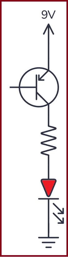
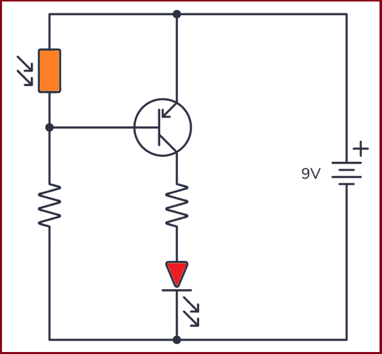
A diode will block or let current flow, depending on how you connect it in a circuit. Below you can see an example circuit.
In the circuit above the diode is connected in the right direction. This means current can flow through it so that the Light-emitting diode (LED) will light up.
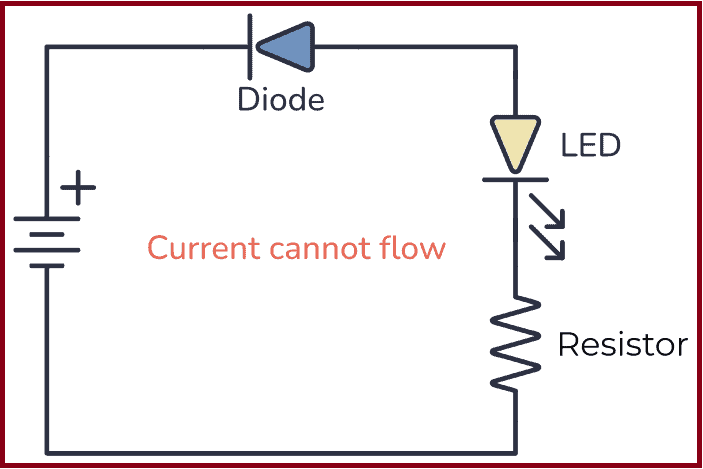
But what happens if we connect it the other way around?
In this second circuit, the diode is connected the wrong way. This means that no current will flow in the circuit and the LED will be turned OFF.
What Is a Diode Used For?
A standard diode can be used for a range of things, from creating sound effects to power supplies. Below, you can see a few circuit examples with an explanation of what the diode is used for:
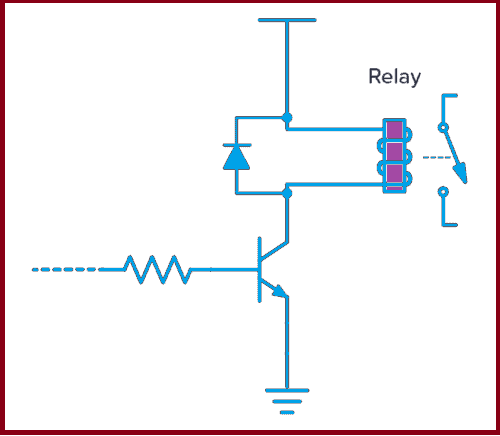
Sound Effects Clipping: By placing two diodes in parallel in opposite directions, you can get a clipping effect which creates an overdrive sound effect, often used in guitar pedals.
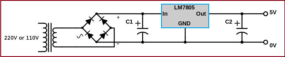
Converting from AC to DC: Sometimes diodes are used to convert from AC to DC by placing four rectifier diodes to create a bridge rectifier. This is often used after a transformer in a power supply, followed by a voltage regulator.
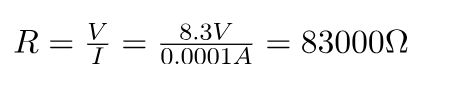
Protecting from voltage spikes: Components like motors and relays are basically inductors, which means their current will try to keep on flowing after the power is shut off. Diodes are used to safely discharge them.
How a Diode Works
The diode is created from a PN junction. You get a PN junction by taking a negatively doped and positively doped semiconductor material and putting it together.
At the intersection of these two materials, a depletion region appears. This depletion region acts as an insulator and refuses to let any current pass.
When you apply a positive voltage from the positive side to the negative side, the depletion layer between the two materials disappears and the current can flow from the positive to the negative side.
When you apply a voltage in the other direction, from the negative to the positive side, the depletion region expands and resists any current flowing.
How To Test Diodes With a Multimeter
You can test diodes with a multimeter to find the forward voltage. To test your diode, you need a multimeter with a diode function. If you see a diode symbol on your multimeter, that’s most likely your diode function.
Connect the positive test lead to the diode’s anode.
Connect the negative test lead to the diode’s cathode.
The multimeter display will show you the forward voltage of your diode.
Things To Note About Diodes
You have to apply enough voltage in the “right” direction – from positive to negative – for the diode to start conducting. Usually, this voltage is around 0.7 V to 1 V.
It has limits and cannot conduct unlimited amounts of current.
Diodes are not perfect components. If you apply voltage in the wrong direction, there will be a little bit of current flowing. This current is called leakage current.
If you apply a high enough voltage in the “wrong” direction, the diode will break down and let current pass in this direction too.
Types of Diodes
There are many different types of diodes. The most common ones are:
Signal diode
Rectifier diode
Zener diode
Light-Emitting Diodes (LED)
Schottky Diode
Photodiode
PIN diode
Signal and rectifier diodes are pretty much the same things except that rectifier diodes are built to handle more power.
Zener diodes are diodes that make use of the breakdown voltage when applying voltage the “wrong” way. They act as very stable voltage references.
Schottky Diodes have a lower forward voltage drop and faster switching speeds than standard signal diodes.
Photodiodes are diodes that are sensitive to light. They let current flow through them when exposed to light.
Light-Emitting Diodes (LED) are components that light up when current flows through them.
The Most Standard Diodes
Rectifier Diode
The rectifier diode is typically used for rectifying alternating current (AC) to direct current (DC). They can usually handle big currents and voltages. Sometimes referred to as power diodes.
Signal Diode
The signal diode works the same way as the rectifier diode. But it can only handle small currents and voltages. It is faster than the rectifier diode and is sometimes referred to as a high-speed diode.
The most typical signal diode is the 1N4148.
Zener Diode
The Zener diode is a component that will become very conductive (meaning that it will allow lots of current) for a certain voltage. This voltage is called the Zener voltage.
What this means is that the voltage drop over the Zener diode will not exceed the Zener voltage. The Zener diode is often used as a stable voltage reference.
Other Types of Diodes
Schottky Diode
The Schottky diode is very similar to a standard small-signal diode. The difference is that the Schottky diode has a lower voltage drop over its terminals. Normal diodes have about 0.7V voltage drop, but the Schottky has only 0.3V.
It is also much faster and is therefore often used in RF circuits.
Light Emitting Diode (LED)
A light-emitting diode or LED is a diode that emits light when forward-biased. It is available in several different colors, even ultra-violet and infrared.
Read more about different LED types.
Photodiode
A photodiode is a diode that conducts when it detects light. Could be used to receive infrared signals from a remote control. Or to create a light sensor
Rectifier Diode
The rectifier diode lets you convert alternating current (AC) to direct current (DC). In this guide, you are going to learn how this component works and some of the circuits you create by using one.
Diodes are one of the basic electronic components in electronics. There are many types of diodes, but the most common one is probably the rectifier diode. It allows current to flow in only one direction and by connecting it a certain way, you can convert AC to DC.
The rectifier diode is made just like any other normal diode, but instead of being designed for small currents, it’s designed for large currents and voltages. This makes it ideal to use in power supplies.
The diode symbol is made up of a triangle pointing to a straight line. The triangle represents the direction the current can flow through the diode. For example, in the picture above, the current can move to the right. But it can’t flow the other way.
How to Use a Rectifier Diode
Rectifier diodes allow current to flow in only one direction, from anode to cathode, also called Forward Bias. The rectifier diode in forward bias is made by connecting the anode to the most positive side and the cathode to the most negative side. You can see this in the example below:
In the above picture, the diode is forward-biased, which means that current can flow through it and the LED will light up. When you use a rectifier diode in this way, it acts similar to a closed switch that allows current to flow through the circuit.
What happens if you reverse the connection of the diode, like this?
When the positive terminal of the power supply is with the cathode and the negative terminal with the anode, the diode is Reverse Biased. With this type of polarization, current can’t flow through the rectifier diode, therefore the LED won’t light up in the above circuit.
What is a Half-Wave Rectifier?
In the examples above, the rectifier diode circuits used a DC power supply, which means a voltage with a fixed value. However, when this diode is connected to an AC power supply, that is where the “rectifying” property comes into play.
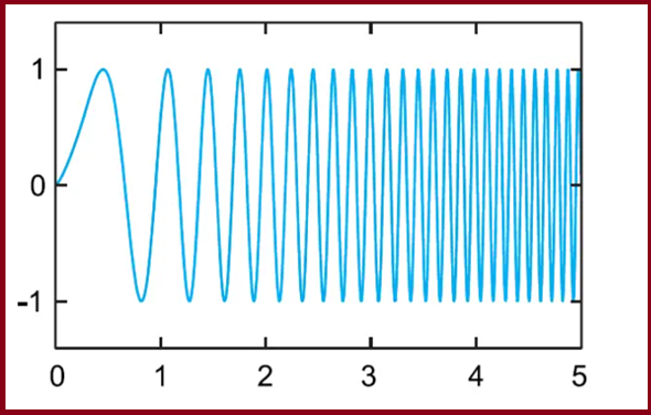
An AC power supply provides voltage in periodic oscillations rather than a constant value, with a positive half-cycle and a negative half-cycle, like so:
This kind of voltage is what you find in the outlets in your home. Yet, when you look at most of the electronics in your home, like your phone or laptop, you’ll find they need DC voltage to function. This is why you need rectifier diodes; they help you convert AC into DC.
Converting from AC to DC with a Rectifier Diode
The most significant step in converting AC into DC is the rectifying process, which means that it makes the negative half-cycles disappear. The simplest way to do this is with the following half-wave rectifier circuit:
Only one diode is required to construct a half-wave rectifier. During the positive half-cycle of the AC voltage, the diode is forward-biased and the current can flow through the diode. In the negative half-cycle of the AC voltage, the diode is reverse-biased and the flow of current is blocked.
What you get from this circuit is a final output that is simply the positive half-cycle waveform.
What is a Full-Wave Rectifier?
When you only get the positive voltage values with a half-wave rectifier, the negative half-cycle gets wasted. The solution to this problem is a full-wave rectifier, which lets the positive half-cycle flow and converts the negative half-cycles into positives.
In the devices you use, full-wave rectifiers are what are most commonly used to convert AC voltage to DC voltage.
A full-wave rectifier circuit made with diodes is called a diode bridge. Check out the diode bridge in the circuit below:
The diode bridge consists of four diodes – D1, D2, D3, and D4 – that are connected together. You can see how D1 and D3 share the same cathode, while D4 and D2 are connected by the anode. At the same time, the cathode of D4 is attached to the anode of D1, and the cathode of D2 is placed in the anode of D3.
The Positive Half-Cycle
During the positive half-cycle of the power supply, diodes D1 and D2 can conduct, while diodes D3 and D4 cannot because they are reverse-biased. With this arrangement, the positive half-cycle gives you a current that flows through the circuit, like so:
The Negative Half-cycle
During the negative half-cycle, diodes D3 and D4 conduct, while diodes D1 and D2 do not. Even though the circuit now receives the negative half-cycle, you can see in the picture below how the current flows through the load (output) in the same direction as before. That’s how this circuit turns the negative half-cycles into positives.
What are Some Common Rectifier Diodes?
When you need to choose a rectifier diode, you have to consider some characteristics, for example:
Peak reverse voltage: this is the maximum voltage the diode can withstand in reverse bias before breakdown.
Maximum forward current: the maximum value of the forward current that the diode can carry without damaging the device.
Peak surge current: the maximum current surge that a diode can handle for a short period of time.
Maximum voltage drop: this is the voltage that stays in the diode when it is forward-biased. Commonly, it will be 0.7v for diodes made of silicon.
The following table contains a list of the most common rectifier diodes and their characteristics.
Diode name
Peak reverse voltage
Max. forward current
Peak surge current
Max voltage drop
1N4001
50
1 A
30 A
1.1
1N4002
100
1 A
30 A
1.1
1N4003
200
1 A
30 A
1.1
1N4004
400
1 A
30 A
1.1
1N4007
1000
1 A
30 A
1.1
1N5402
200
3 A
200 A
1.2
1N5406
600
3 A
200 A
1.2
1N5408
1000
3 A
200 A
1.2
Laser Diode:
A laser diode is a cool component that you can do a lot of fun stuff with, from engraving wood to creating a light show or giving your robot eyes They range from super cheap to more expensive.
Most types are really easy to use too, once you learn the basics
What Is a Laser Diode?
A laser diode type of diode that creates a very strong and focused beam of light. It is made from a material that can make light waves move in a straight line. This makes the laser beam very powerful and useful for many things, such as cutting or engraving materials, reading data, or even playing with your cat!
A regular Light-Emitting Diode (LED) gives off light in all directions. The laser diode is different because it sends light in only one direction .
How To Use a Laser Diode
You can get laser diodes as standalone components or as modules. For most hobbyist projects, the module is the best choice because it is simpler to use.
Note! Laser diodes can be dangerous and should be handled with care. Always wear appropriate eye protection when working with laser diodes and follow all safety precautions recommended by the manufacturer.
Using a Laser Module
If you buy a laser module, you only have to connect it to the right voltage for it to work. That makes it super easy to for example connect to an Arduino.
A laser module is an all-in-one device that contains everything you need for the laser diode to work properly. It usually comes in a housing with a black wire and a red wire coming out of it. To turn it on, you just need to connect the correct voltage with plus to the red wire and minus to the black wire.
The exact voltage you need depends on your module. The seller should be able to provide you with that information, or you’ll find it in the datasheet.
Sometimes a laser module comes mounted on a board. On some of these boards, you’ll also find a potentiometer that you can use to adjust the power of the laser.
A common low-power laser diode board is the Arduino laser module Keyes. It has three pins; two for connecting 5V and GND, and one for turning the laser on and off.
Using a Single Laser Diode
If you buy a single laser diode as a standalone component, you need to set up a driver circuit that controls the current through the laser diode.
A laser diode needs a driver circuit to work properly, and the driver circuit needs to give the laser a constant current. Below you’ll find a simple constant current circuit that uses the LM317 voltage regulator.
The circuit above was designed to power the OPV332 laser diode. The potentiometer (RV1) enables you to adjust the current up and down to adjust the power of the laser. R1 limits the current to 12 mA, which is the absolute maximum this diode can handle.
If you’re using a different diode, you’ll need to adjust the values so that it fits your specific laser diode
Laser Diode With Three Legs
Some laser diodes have three legs:
The first pin is the anode, which is the positive pin that provides power to the laser diode.
The second pin is the cathode, which is the negative pin of the laser diode.
The third pin is the monitor photodiode, which is used to monitor the output power of the laser diode. The monitor photodiode measures the amount of light that the laser diode emits. You can feed this back to the driver circuit to ensure that the laser diode is operating at the correct power level.
The monitor photodiode is a key feature of VCSEL laser diodes because it allows for precise control over the output power of the laser. This is important in applications where the laser beam needs to be precisely controlled, such as in fiber-optic communication systems or in 3D sensing applications.
Typical Laser Diode Projects
Laser diodes can be used for a lot of fun projects. Here are a few examples to get you thinking about what’s possible.
Laser engraving and cutting: You can use laser diodes to engrave or cut various materials, such as wood, plastic, and leather. You can do this with a DIY laser engraver or cutter, or by repurposing a laser module from a DVD burner. Check out this DIY laser engraver from Instructables.
Laser light shows: You can use laser diodes to create dazzling laser light shows. By controlling the color, intensity, and pattern of the laser beams, you can create a wide range of visual effects. Check out this instructional video on how to build one.
Robotics: You can use a laser diode as a component in a laser rangefinder to give your robot eyes. You can also use them to create laser-based communication systems between robots or other devices. Here’s an Arduino-based LiDAR project you can check out.
How Much Power Do You Need?
The power of a laser is an important thing to keep in mind. If you want to create a laser cutter that can cut through different materials, you’ll need much more power than if you’re making a simple laser pointer to play with your cat.
Here’s a quick overview of the power needed for different applications:
Laser pointers: a few milliwatts up to a few hundred milliwatts
Engraving on softer materials like wood or leather: a few watts
Cutting harder materials such as acrylic or metal: several watts to tens of watts
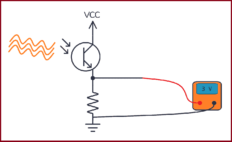
Photodiode :
A photodiode is a PN-junction diode that consumes light energy to produce an electric current. They are also called a photo-detector, a light detector, and a photo-sensor. Photodiodes are designed to work in reverse bias condition. Typical photodiode materials are Silicon, Germanium and Indium gallium arsenide.
What Is a Photodiode?
A photodiode is a diode that senses light. It has two legs and comes in various shapes and packaging. When light hits a photodiode, current flows through it in one of two ways: either a small current is created from the light, or the light allows a larger current to flow through.
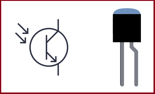
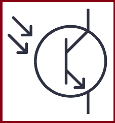
The photodiode symbol looks like the symbol for the light-emitting diode, except that its arrows point inward.
The photodiode symbol
How To Use a Photodiode
When you operate a photodiode without any bias voltage, shining light on it generates a small voltage across its terminals.
If you connect a resistor across it, a very small current flows through the resistor. This is called photovoltaic mode and works best in low-frequency conditions
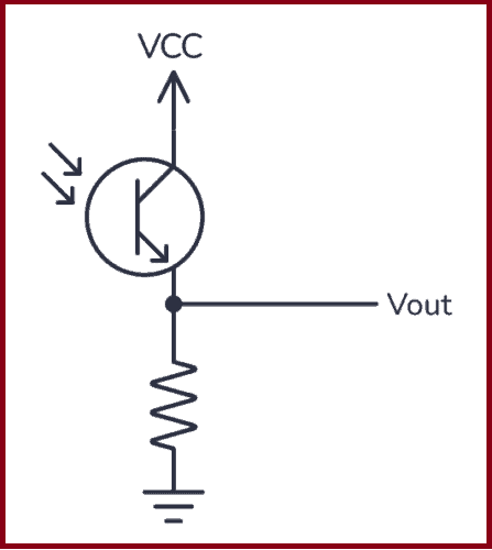
On the other hand, when it is reverse biased, i.e. the anode is connected to the negative voltage and the cathode to the positive voltage, it is in photoconductive mode. In this mode, it works more like a switch. Light on the photodiode “closes the switch” and current flows through the photodiode:
In this mode, it can switch on and off much faster. Photodiodes are usually used in this mode.
How Does a Photodiode Work?
Internally, a photodiode has a p-n junction, which is formed when a p-type semiconductor material is fused with an n-type semiconductor material. A p-type semiconductor material has holes as positive mobile charge carriers, while an n-type semiconductor material has electrons as negative mobile charge carriers.
Since the p-n junction has oppositely charged mobile carriers, they neutralize each other and form a depletion region at the juncture. It is called a depletion region because it is devoid of any mobile charge carriers. The part of the p-type material in the p-n junction is devoid of holes, so it becomes negatively charged. Similarly, the part of the n-type semiconductor in the p-n junction becomes positively charged.
When photons – or light – of sufficient energy fall on the p-n junction of the photodiode, they break and ionize the covalent bonds of the immobile atoms. This generates new electron-hole pairs. This phenomenon is called the photoelectric effect. The generated electrons are swept toward the n-type material (because the depletion region of the n-type material is positively charged). The holes are swept towards the p-type material (because the depletion region of the p-type material is negatively charged). This flow of charge leads to photocurrent or simply current.
In other words, a photodiode senses light and produces current as output. A photodiode is also called a photo sensor, photodetector, or light detector.
Typical Photodiode Circuits
Photodiodes can be used in a variety of ways, but the most commonly used circuits are the two below that use operational amplifiers (op-amps).
Two different ways to use a photodiode
In the photovoltaic circuit, you connect the photodiode in forward-biased mode. The anode of the photodiode is connected to the non-inverting terminal and the cathode to the inverting terminal of the op-amp. When light falls on the photodiode, it generates a small voltage and current. The op-amp amplifies this and outputs a voltage. The size of the voltage depends on the value of the feedback resistor RF.
In the photoconductive circuit, you connect the photodiode in reverse-biased mode. In the circuit diagram above, VR is a negative voltage. When light hits the photodiode, a small current passes through it, and an amplified voltage is available at the output.
In both cases, the op-amp is working as a trans-resistance amplifier or a current-to-voltage amplifier.
Types of Photodiodes
There are four main types of photodiodes:
PN photodiode: a simple p-n junction photodiode used in reverse-biased mode.
PIN photodiode: a p-n junction photodiode with an intrinsic semiconductor layer between the p- and n-type material at the juncture. It is used when a greater surface area for light exposure is needed.
Avalanche photodiode: a p-n junction photodiode that can be used in deep reverse-biased conditions. It has a higher photovoltaic current as a larger number of electron-hole pairs get generated in the p-n junction.
Schottky photodiode: this is made of multiple Schottky diodes and operates at a higher speed and at larger wavelengths.
What’s the Difference Between a Photodiode and a Phototransistor?
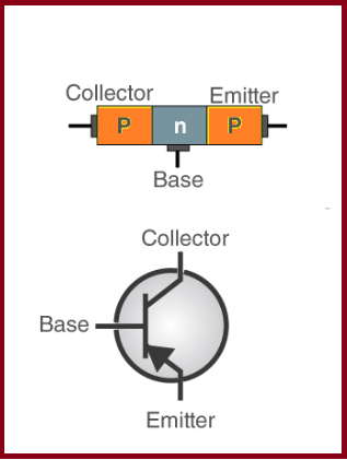
The photodiode is very similar to the phototransistor. They are both light-triggered devices that are connected in the same way in a circuit.
The difference is that a phototransistor is a transistor with a photodiode connected to its base. When light hits the photodiode, current flows through the base, and the transistor turns on so that current can flow through it.
Applications of Photodiode
Photodiodes are used in simple day-to-day applications. The reason for their prominent use is their linear response of photodiode to light illumination.
Photodiodes with the help of optocouplers provide electric isolation. When two isolated circuits are illuminated by light, optocouplers are used to couple the circuit optically. Optocouplers are faster compared to conventional devices.
Photodiodes are used in safety electronics such as fire and smoke detectors.
Photodiodes are used in numerous medical applications. They are used in instruments that analyze samples, detectors for computed tomography and also used in blood gas monitors.
Photodiodes are used in solar cell panels.
Photodiodes are used in logic circuits.
Photodiodes are used in the detection circuits.
Photodiodes are used in character recognition circuits.
Photodiodes are used for the exact measurement of the intensity of light in science and industry.
Photodiodes are faster and more complex than normal PN junction diodes and hence are frequently used for lighting regulation and optical communication.
Schottky Diode:
The schottky diode is a type of metal – semiconductor junction diode, which is also known as hot-carrier diode, low voltage diode or schottky barrier diode. The schottky diode is formed by the junction of a semiconductor with a metal. Schottky diode offers fast switching action and has a low forward voltage drop
Single Schottky Diode (left) and a Schottky Pair (right)
What Is a Schottky Diode?
Diodes are components that normally only let current flow in one direction. Like a regular diode, the Schottky diode allows current to flow in the forward direction when enough forward voltage is applied.
Schottky Diode Symbol
However, while a regular PN junction diode is made by connecting p-type and n-type semiconductors, the Schottky uses metals like gold, tungsten, platinum, or aluminum instead of the p-type semiconductors.
This difference in construction gives it some unique properties that make it very useful for some specific applications. The Schottky diode has a relatively small voltage drop, usually between 0.15 to 0.45 V. This low forward voltage enables it to switch on and off much faster than traditional PN junction diodes.
How to Use Schottky Diodes
The Schottky diode works like any other PN junction diode, but faster. Current can flow through it only when it’s forward-biased. To make this happen, you must connect the anode to the most positive side and the cathode to the most negative side. Take a look at this example:
You can see above that the diode is forward-biased. That means the LED will light up because current can flow through it. When you use a Schottky diode like this, it’s like a fast switch that is closed and lets the current flow through the circuit.
Now let’s rotate the diode:
When the Schottky is reverse biased (cathode on the most positive side and anode on the most negative side) current can’t flow, so it acts like an open switch and the LED won’t turn on.
Schottky Diode vs PN Junction Diode
Schottky diodes are often compared to the PN junction diode. It’s because they behave very similarly. To understand the differences between them, take a look at their V-I characteristic curves:
Consider that the curves above correspond to semiconductors made of silicon. You can see that the Schottky diode behaves a lot like a standard PN junction diode, except for one thing: the knee voltage – which is when it starts conducting – is much lower at around 0.4 V.
Thanks to its lower forward voltage drop, the Schottky diode can carry more current than a typical PN junction diode. The formula for power is power = volts x current (P = V*I). This means that a smaller forward voltage drop at a given current will result in less power dissipation than the PN junction diode. In plain English, the Schottky diode doesn’t get as hot as a regular diode.
Also, since Schottky diodes don’t have a p-type semiconductor, they have a low recovery time. This allows faster switching between on and off states.
Differences Between Schottky Diode and PN Junction Diode
Schottky diode
PN junction diode
In this diode, the junction is formed between the n-type semiconductor and the metal plate
In this diode, the junction is formed between the p-type and n-type semiconductors
The forward voltage drop is low
The forward voltage drop for pn junction diode is more
Reverse recovery loss and reverse recovery time are very less
Reverse recovery loss and reverse recovery time are more
It is a unipolar device
It is a bipolar device
The conduction of current happens only due to the movement of electrons
The conduction of current happens due to the movement of electrons and holes
Applications of Schottky Diode
Some common applications of the Schottky diode include:
Reverse current protection
Solar cell applications
Discharge protection
Voltage clamping
Switched-mode power supplies
Logic gates circuits
Radio frequency mixer and detector diodes
Schottky-clamped Transistor
A Schottky-clamped transistor is a type of BJT transistor. It has a Schottky diode connected across its base-collector junction and it is designed to switch on and off very quickly.
The Schottky diode in the transistor allows for faster switching by reducing the time it takes for the transistor to turn on and off. This is useful in applications where you need to switch things on and off rapidly. It also to helps reduce the amount of energy lost when the transistor is on, making the transistor more efficient. This means it can do its job while using less power.
Another advantage of a Schottky-clamped transistor is that it can handle voltage spikes and sudden changes in voltage without getting damaged. This makes it more reliable and durable in circuits where there might be fluctuations in voltage.
Schottky-clamped transistors are commonly used when you need fast switching and efficient operation, such as in power supplies, amplifiers, and digital circuits. They are especially good for applications involving radio signals and high frequencies.
Advantages of Schottky diode
Following are the advantages of Schottky diode:
The capacitance of the diode is low as the depletion region of the diode is negligible.
The reverse recovery time of the diode is very fast, that is the change from ON to OFF state is fast.
The current density of the diode is high as the depletion region is negligible.
The turn-on voltage of the diode is 0.2 to 0.3 volts, which is very low.
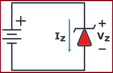
Zener Diode Basics
A Zener Diode, also referred to as a breakdown diode, is a specially doped semiconductor device engineered to function in the reverse direction. When the voltage across a Zener diode’s terminals is reversed and reaches the Zener Voltage (also known as the knee voltage), the junction experiences a breakdown, allowing current to flow in the opposite direction. This phenomenon, known as the Zener Effect, is a key characteristic of Zener diodes
What Is a Zener Diode?
A Zener diode is a type of diode that is often used for voltage regulators and shaping waveforms.
Its symbol is an arrow pointing towards a crooked line. There are actually three different ways you can draw the Zener diode symbol in schematics:
Three ways to draw the Zener Diode Symbol
While a normal diode only allows current to flow through a circuit when it is forward-biased (current going from anode to cathode), the Zener diode also works when it is reverse-biased (current going in the opposite direction).
With standard diodes, if you place it in reverse, no current flows.
At least, so it appears. But actually, if you apply enough voltage in reverse, current will start to flow.This voltage is called the breakdown voltage of the diode.
For example, the rectifier diode 1N4001 has a breakdown voltage of 50V.
The Zener diode is basically the same as the standard PN junction diode. However, it is specially designed to work in reverse bias with a low and specified reverse breakdown voltage.
So, why is that interesting?
Because you’re not limited to the standard forward voltage of 0.7V. You can design the breakdown voltage to be for example 3.3V or 12V – or many other voltages. The manufacturers call this Zener Voltage (Vz).
This means a Zener diode can act as a voltage regulator because it keeps the breakdown voltage at a nearly constant value across its terminals.
How To Make A Zener Diode Voltage Regulator
Making a voltage regulator is easy with the Zener: Just add a resistor!
Here’s how it works:
When a voltage (must be higher than the Zener voltage) is applied across the resistor and Zener diode, the diode starts conducting in reverse and keeps the voltage drop across it at a constant value of 3.3V.
The rest of the voltage drops across the resistor. This means the resistor acts as a current-limiting resistor so that you can easily calculate the current by using Ohm’s law.
The resistor (RS) limits the maximum current that can flow through the circuit. If there is no load connected to the circuit all the current flows through the Zener diode, causing it to dissipate its maximum power.
A smaller value of resistor RS gives you a higher maximum current. But at the same time, you have to make sure that you don’t exceed the maximum power rating of the Zener. Therefore, it’s important to choose the right value of series resistance.
Example: Choosing a resistor for a 12V to 3.3V voltage regulator
In this example, you’re going to use a Zener diode that can handle up to 2W of power. What’s a suitable value for the resistor (RS)?
First, you need to find the maximum current that can flow through the Zener diode:
That means that the minimum value of the resistor is:
So a value of 14.5 Ω is the absolute minimum. But you can use higher resistances of course.
Next, you need to check how much current your load needs. The load resistor is 1 kΩ, so its current is calculated as follows:
That’s much lower than the 0.6A you’d get from the 14.5 Ω resistor, so no problem here.
If you want to use a higher resistor value, just use the following formula with your chosen resistor value and make sure that it’s above the current you need for your load:
For example, if you want to use a 100 Ω resistor, this would give you a maximum current of:
Still, high above the needed 0.0033A for the load, so you’re good to go.
That said, Zener diodes have their disadvantages. Check out this article about why Zener diodes make lousy voltage generators.
Wave-Shaping With the Zener
In the previous example, you saw how the Zener works with DC power. However, what happens when it’s used with AC power? How would it react to a constantly changing signal such as an audio signal?
Check out the following circuit:
In the above diagram, the Zener diode has a VZ of 5V, so if the waveform exceeds this limit, the diode will “clip off” the excess voltage from the input, resulting in a waveform with a flat top maintaining a constant output of 5V.
When forward-biased, the Zener diode behaves like a regular diode. So when the waveform reaches negative values below 0.7V, the Zener acts like a typical rectifier diode, resulting in output clipping at -0.7V.
Zener Diode Characteristics (The I-V Graph)
The I-V characteristics curve of a Zener diode is shown in the image above. By studying this graph, it becomes clear why Zener diodes are employed in reverse bias.
By observing the behavior of a Zener diode, you can notice that as the reverse voltage rises, the reverse current also increases gradually until it hits the Zener knee current, IZ (min). At this point, the breakdown effect starts, and the Zener impedance (ZZ), which is the internal resistance of the diode, begins to rapidly decrease as the reverse current increases.
In general, the breakdown voltage of the Zener (VZ) is fairly constant, although it increases slightly with increasing Zener current (IZ). VZ is commonly set at a value of the Zener current known as the IZ (min).
A Zener diode’s ability to maintain almost constant voltage in its breakdown region makes it suitable for regulating voltage even in the simplest voltage regulator applications.
A voltage regulator’s main role is to deliver a steady output voltage to a load connected in parallel. This is even when the supply voltage has ripples or the load current varies. Zener diodes can maintain a constant voltage output as long as their reverse breakdown region holding current does not drop below IZ (min).
Zener Diode Specifications
Some commonly used specifications for Zener diodes are as follows:
Zener/Breakdown Voltage – The Zener or the reverse breakdown voltage ranges from 2.4 V to 200 V, sometimes it can go up to 1 kV while the maximum for the surface-mounted device is 47 V.
Current Iz (max) – It is the maximum current at the rated Zener Voltage (Vz – 200μA to 200 A)
Current Iz (min) – It is the minimum value of current required for the diode to break down.
Power Rating – It denotes the maximum power the Zener diode can dissipate. It is given by the product of the voltage of the diode and the current flowing through it.
Temperature Stability – Diodes around 5 V have the best stability
Voltage Tolerance – It is typically ±5%
Zener Resistance (Rz) – It is the resistance to the Zener diode exhibits.
Application of Zener Diode
Following are the applications of Zener diode:
Zener diode as a voltage regulator:
The zener diode is used as a Shunt voltage regulator for regulating voltage across small loads. The Zener diode is connected parallel to the load to make it reverse bias, and once the Zener diode exceeds knee voltage, the voltage across the load will become constant. The breakdown voltage of Zener diodes will be constant for a wide range of currents.
Zener diode in over-voltage protection:
When the input voltage is higher than the Zener breakage voltage, the voltage across the resistor drops resulting in a short circuit, this can be avoided by using the Zener diode.
Common Zener Diode Voltages
Here you have a table with the most common Zener voltages in diodes of 0.3 W and 1.3 W.
A capacitor is a basic electronic component that works like a tiny rechargeable battery with very low capacity. Capacitors are used to create oscillators, time delays, add a power boost, and much more.
Like most components, the easiest way to understand how a capacitor works is to see with your own eyes what it does in a circuit.
What Is a Capacitor?
A capacitor is made up of two metallic plates with a dielectric material (a material that does not conduct electricity) in between the plates. And there’s actually no more magic to it. It’s that simple and you can even make your own capacitor by using two sheets of aluminum foil with a piece of paper in between.
When you apply a voltage across the two plates, a current flows as the voltage tries to push electrons through the capacitor. But electrons can’t flow through the dielectric between the plates, so instead the electrons will build up on one plate and leave the other plate.
Eventually, the side where the electrons gather won’t have room for more electrons, so the current stops flowing. When that happens, the capacitor is fully charged. The amount of electric charge the capacitor can hold is called its capacitance.
Electrons don’t like being crowded together on one plate. They want to go over to the side with fewer electrons. So if you provide a path for the electrons to flow (for example by connecting a resistor between its legs) the electrons will flow back to the other side until there’s an equilibrium of electrons on both sides of the capacitor again.
How Capacitors Work
a capacitor works like a tiny rechargeable battery with very low capacity.
But a capacitor is usually charged and discharged in a fraction of a second. So it’s not used for the same purpose as a battery. Instead, it’s used for things like adding a time delay, creating oscillators, and as tiny backup generators for microcontrollers.
A Simple Capacitor Circuit
If you want to understand how the capacitor works without reading theory and formulas – then build this circuit:
You can use a 9V battery, a standard Light-Emitting Diode (LED), and a 1000 µF capacitor. The resistor value can be around 500-1000 ohms.
Connect the battery, and you should see the LED turn on. Nothing special yet.
But when you disconnect the battery, something interesting happen The LED stays lit for a few more seconds without being connected to the battery!
This happens because the capacitor is first charged by the battery. When you disconnect the battery, the stored charge in the capacitor flows through the resistor and LED and thereby keeping the LED on for a few more seconds, until the capacitor is discharged.
So the capacitor works similarly to a battery – it can be charged and discharged.
Charging a Capacitor
If you want to get a really good understanding of capacitors and how to use them in your circuits, there are two important things you need to know:
What happens to the voltage across the capacitor when you charge it?
What happens to the current through the capacitor when you charge it?
The Voltage Across a Capacitor
If you charge a capacitor from a 9V voltage source, the voltage across the capacitor will eventually become 9V – but not immediately. At the moment when you start charging it, the voltage will start at 0V.
But the voltage increases quickly, so if you try to measure it with a multimeter, you won’t be able to read 0V.
After some time, when it is fully charged, the voltage across it becomes 9V (or whatever voltage you used to charge it):
The voltage increases quickly in the beginning, then slowly at the end. The time it takes to charge the capacitor depends on how much current is flowing. In the example above, it would be determined by the resistor R1.
The Current Through a Capacitor
When you start charging a capacitor, the current flows freely without any resistance in the very beginning.
As the capacitor charges, the resistance increases so that less and less current can flow. When the capacitor is fully charged no more current flows through it:
Here’s a simplified graph that shows how the current slows down with charging time:
Types of Capacitors
There are many different capacitor types. But when you start out, the main thing to remember is the difference between a polarized and a non-polarized capacitor.A polarized capacitor needs to have its positive side connected toward plus, and the other side toward minus. Otherwise, you might destroy it. This is a side-effect of how large-value capacitors are made.
A non-polarized capacitor can be connected either way, it doesn’t matter.
You can recognize one or the other in a schematic diagram by looking at the capacitor symbol. The polarized capacitor will have a plus marking.
Polarized vs Non-Polarized Capacitors
If you need a polarized capacitor, you need something called an electrolytic capacitor. The most common types are Aluminium and Tantalum. Aluminum is the cheapest of the two. But if you need a smaller and more durable capacitor, you should choose the Tantalum type.
If you need a non-polarized capacitor, the most common types are Ceramic and Film.
Ceramic capacitors are small and cheap. It’s the most common choice for non-polarized capacitors. But if you have any special requirements like low tolerance, high reliability, or a capacitor that is able to operate under high temperatures, then choose a Film capacitor.
In the photo below you can see a ceramic capacitor on the right and an aluminum electrolytic capacitor on the left:
Application
Capacitors are used for a lot of things, such as:
Adding a time delay in a circuit
Making oscillators
Creating audio filters (such as low-pass and high-pass filters)
Remove ripple in a power supply
Adding short bursts of energy (for example to power the flash of a camera)
Stabilizing the voltage supply of a microcontroller
Example 1: Add a Time Delay
In this example, when the input signal goes low, the output from the 555 timer goes HIGH for a certain period of time before going back to LOW. You could for example use it to turn on the lights on your porch for 2 minutes every time an IR sensor detects that there is someone present.
In this circuit, it’s the capacitor C1 that adds the time delay. All the 555 timer does is provide the logic to check the voltage level across the capacitor against a threshold level, then turn the output on or off accordingly.
Example 2: Create an Oscillator (Blinking an LED)
In this blinking LED example circuit, the voltage across the capacitor is interpreted as either a 1 (HIGH) or a 0 (LOW) by the NOT gate.
The output becomes the opposite of the input. So if the input is LOW, the output is HIGH. When the output is HIGH, the output voltage will start charging the capacitor so that it eventually also ends up HIGH. But when it does, the output will switch to being LOW. When the output is LOW, it will make the capacitor start discharging so that it eventually also ends up being LOW.
Example 3: Design Audio Filters
You can combine capacitors and resistors to form filters. A filter removes specific frequencies from an audio signal and lets others pass through. For example, if you want to remove high frequencies and let the lower frequencies pass through (e.g. in a sub-woofer), you can build a low-pass filter:
Example 4: Decoupling Capacitors for Microcontrollers
Imagine a typical alarm clock, powered by the electrical outlet on the wall in a house. If the power goes down, most alarm clocks have a backup battery that will take over and power the alarm clock until the power comes back on so that the time is not reset.
If you have a circuit with a microcontroller running some code and the supply voltage to the microcontroller drops for only a split second, the microcontroller stops what it is doing and restarts. That can cause all sorts of problems, so you don’t want this.
By using a capacitor, the capacitor can supply power for the microcontroller for a short period so that the microcontroller doesn’t restart. This way it will filter out noise on the power line.
A capacitor used for this purpose is called a decoupling capacitor.
Typical Capacitor Values
You have two important values for capacitors; capacitance and voltage rating.
The capacitance value of a capacitor is its “capacity” to store energy. A higher capacitance value means it can store more energy than a lower value. It is given in Farads (F).
The voltage rating is the maximum voltage a capacitor can handle. So if you have a circuit where the voltage across the capacitor can reach 12V, you need a capacitor with a voltage rating of 12V or more. It is recommended to use a capacitor rated for more than 12V so that you have some safety margin.
The capacitance value is given in Farad (F). But 1 F is a very high value. Usually, capacitor values are given as microfarad (µF), nanofarad (nF), or picofarad (pF). In the table below, you can see these values written out:
Prefixes
Compact Value
Written-Out Value
1 F
100 F
1 Farad
1 µF
10-6 F
0.000001 Farad
1 nF
10-9 F
0.000000001 Farad
1 pF
10-12 F
0.000000000001 Farad
If you look closely, you’ll see that for example, 100 nF is the same as 0.1 µF. This is good to remember. Because it’s very common to use both 0.1 µF and 100 nF to describe the same value.
Identifying A Capacitor Value
On big aluminum capacitors, the values are usually written out in cleartext. For example, if it says 22 µF 450V, that’s the capacitance value and the voltage rating.
But often on smaller capacitors, you instead have cryptic numbers. Like 102, 223, or 474. In these cases, the first two numbers make up the base pF value, and the last is the number of zeroes you add after:
102: 10 pF with 2 zeroes after is 1000 pF. Which is the same as 1 nF. 104: 10 pF with 4 zeroes after is 100000 pF. Which is the same as 100 nF. Or 0.1 µF. 223: 22 pF with 3 zeros after is 22000 pF. Which is the same as 22 nF. 474: 47 pF with 4 zeroes after is 470000 pF. Which is the same as 470 nF. Or 0.47 µF.
The inductor is a simple component, and how it works is also pretty simple. The only problem is that most explanations do not explain it in a simple way.
So, what is an inductor? Well, it’s kind of a strange component. At the most basic level, it is just a coil of wire. And it’s easy to make one — just make some loops with a wire.
But wires actually create magnetic fields. And that means the inductor behaves in an interesting way and can do interesting stuff.
An inductor will resist changes in current.
In the circuit below, you have an LED and a resistor in series with an inductor. And there’s a switch to turn the power on and off.
Without the inductor, this would just be a normal LED circuit and the LED would turn on right away when you flip the switch.
But the inductor is a component that resists changes in current.
When the switch is off, there is no current flowing. When you flip the switch on, the battery will try to get current flowing. That means there is a change in current which the inductor will resist.
So instead of the current going from zero to maximum right away, it will gradually increase up to its maximum current.
(The maximum current for this circuit is set by the resistor and the LED.)
Since the current decides the light intensity of the LED, the inductor makes the LED fade in instead of turning on instantly.
Note: You’d need a very large inductor to be able to see the LED fade in the circuit above. It’s not something that you’d use an inductor for. But use it as a mental image of what the inductor does in a circuit.
What Happens When You Disconnect the Inductor?
The inductor also resists the current from switching off instantly. The current won’t just stop flowing in the inductor in an instant.
So when you switch off the power, the inductor will try to continue the current flow.
It does this by quickly increasing the voltage across its terminals.
It actually increases so much that you can get a little spark across the pins of your switch!
This spark makes it possible for the current to keep flowing (through the air!) for a fraction of a second until the magnetic field around the inductor has broken down.
That’s why it’s common to place a diode in reverse across the coil of a relay or a DC motor (called a flyback diode). This way, the inductor can discharge through the diode instead of creating high voltages and sparks in the circuit.
How Inductors Works
Any wire with current flowing through it has a small magnetic field surrounding it.
When you wind the wire into a coil, the field becomes stronger.
If you wind the wire around a magnetic core, such as steel or iron, you’ll get an even stronger magnetic field.
This is how you create an electromagnet.
The magnetic field around it depends on the current. So when the current changes, the magnetic field changes.
When the magnetic field changes, a voltage is created across the inductor’s terminals that oppose this change.
Application
It’s not that common to see discrete inductors in the typical example circuits for beginners. So if you’re just starting out, you probably won’t come across them just yet.
But they are very common in power supplies. For example, to create a buck or boost converter. And they are common in radio circuits to create oscillators and filters.
What you will come across much more often though, is electromagnets. And they are basically inductors. You’ll find them in almost everything that moves from electricity. Like relays, motors, solenoids, speakers, and more.
And a transformer is basically two inductors wound around the same core.
A resistor is nothing magic. Take a long wire and measure the resistance, and you will realize that resistance is just a normal property of wires (except for superconductors).
Some resistors are made up of just that. A long wire.But you can also find resistors made of other types of materials. Like this carbon film resistor:
Effect of Resistor to Circuit
The resistor is a passive device and doesn’t do anything actively to your circuit.
It’s actually a pretty boring device. If you add some voltage to it, nothing really happens. Well, maybe it gets warm, but that’s it.
BUT, by using resistors, you can design your circuit to have the currents and voltages that you want to have in your circuit.
So the resistor gives the designer control over his circuit! How about that?
How to Work With Resistors
At the beginning of my electronics career, I thought it seemed like resistor were just randomly placed around a circuit and I thought that you didn’t really need them.
For example, I remember seeing a circuit with a 9V battery, a resistor, and an LED. Then I tried using only the battery and the LED, and it still worked!
But after a few seconds, the LED turned really hot. So hot I almost burned my fingers. Then I started to realize that maybe there was something to these resistors.
Series Circuits
Current in Circuits Connected in Series
The current in a series circuit is equal everywhere in the path. The same amount of current flows through all the components. To find the current use Ohm’s law
Resistance in Series Circuits
If you have several resistors connected in series, it’s very easy to find the total resistance. All you have to do is to find the sum of all the resistance values.
Rtotal=R1+R2+R3
Current in Parallel Circuits
The current in parallel circuits can be different from path to path. To find the current of a path, you use Ohm’s law.
Calculating Resistors in Parallel
To calculate the resistance in a parallel circuit, you use the following formula
To find RTOTAL you need to invert both sides, and you’ll end up with this:
Is the current lower after a resistor?
Nooooo!It is not.It’s a common misunderstanding.But let me make it clear:
The current after a resistor is the exact same as it was before the resistor.
A circuit always has a bit of resistance, no matter if it has resistors or not in it.
Even wires have a little bit of resistance.
So let’s imagine a circuit – any kind of circuit – and say that its current is 1 ampere.
If you now add a resistor in series into this circuit – the current of the circuit will be smaller than it was.
So yes, the resistor does reduce the current.
(But the current flowing into the resistor is still the same as the current flowing out.)
This is one of the mindset shifts a beginner has to go through when learning electronics.
But after a few examples and a bit of practice, this becomes obvious. And it becomes much easier to understand what all the circuits actually do.
How To Choose A Pull-up Resistor Value
You can use resistors for many things. In the following 555 timer circuit that was referring to, the resistor R2 is a pull-up resistor with a value of 10 kΩ:
The 10k resistor (R2) is there to make sure the voltage on the pin is held at a stable high level.
“High” as in a value close to the supply voltage.
The reason that I chose the value 10k is that from my experience I know that 10k to 100k pull-up resistors usually work fine in almost all circuits.
I’ve seen this used many times and I’ve tried it myself many times.
But if you don’t know this and you need to find a value, read on.
Choosing a Pull-up Resistor Value
There are two basic guidelines for choosing a pull-up resistor value.You need a value that is:
Not too small
Not too big
Not Too Small
The first factor is to have a value that is not too small.
If the value is too small a lot of current will flow through the resistor, which makes it really warm and could break it.
What is “too small”?
Standard resistors often have a power rating of 0.25W (Watt).
If you look at a worst-case scenario, all the 9V of the voltage source would drop across the resistor.
Power dissipation in a resistor can be calculated with this formula:
We can solve that for R to find the minimum resistance value you need:
With a resistor of 324 Ω you’ll be at the limit of what the resistor can handle if there is a 9V drop over it.
So you want to have a value much higher than this.
If you choose a value of minimum 10-20 times this, you should be fine. For example 5 kΩ as a minimum.
Not too big
The resistor value cannot be too big.
If the resistor value is too big, you get too much voltage drop over it so that the value on the input pin is no longer high enough to be called high.
What is “too big”?
You can use this rule of thumb:
Choose a pull-up resistor value that is at least 10 times smaller than the input impedance of the pin.
(This is because the input impedance and the pull-up resistor will make up a voltage divider. Keeping it 10 times lower assures the drop across the resistor is less than 10%.)
The input impedance of the 555 timer is 10 Megaohms according to electronicsclub And 10 times smaller is 1 MΩ.
That gives you the choice of a pull-up resistor value of anywhere in between 5 kΩ and 1 MΩ.
So as you can see, you can use a range of values here.
Resistor Color Code Calculator (4 and 5-band)
The resistor color code (color bands) on your resistor tells you what value the resistor has. There are usually 4 or 5 bands.
Resistor Color Codes Table
You can find the color bands and the values they represent in the table below:
How To Use The Resistor Color Codes Table
In the resistor color codes table, you have digits, a multiplier, and a tolerance.
The multiplier tells you what you need to multiply your digits with to get the value. The tolerance tells you how accurate this value is.
If your resistor has four color bands:
The first two bands give you the digits
The third band gives you the multiplier
The fourth band gives you the tolerance
If your resistor has five bands instead of four, the first three bands give you the digits. And the following two give you the multiplier and the tolerance.
Example #1
This resistor has four bands. The colors of the bands are yellow – purple – orange – gold.
From the table above we find that this means:
Digit 4
Digit 7
Multiplier 1000
Tolerance 5%
47 multiplied by 1000 is 47000.
So this is a resistor with 47000 Ω (47 kΩ).
A tolerance of 5% means that the real value could be 5% higher or lower than 47 kΩ.
Example #2
This resistor has five bands. The colors of the bands are orange – green – black – red – brown.
From the table above we find that this means:
Digit: 3
Digit: 5
Digit: 0
Multiplier: 100
Tolerance: 1%
350 multiplied by 100 is 35000.
So this is a resistor with 35000 Ω (35 kΩ).
A tolerance of 1% means that the real value could be 1% higher or lower than 35 kΩ.
Types of Resistors and How To Choose One
Your electronic schematic tells you that you need a resistor of 100k Ohms. Ok, so you go to an online store to buy one. But there you get all these choices: Thin film, carbon composition, metal film +++.
“Just give me a freaking 100k resistor man!”, you scream in despair.
Believe me, I know your frustration. It took me a long time to actually bother reading about different types of resistors. So I just chose random resistors for all my electronic circuits. Usually, it worked flawlessly. Maybe I was lucky or maybe I just didn’t identify the resistor as the problem when I had a problem.
Anyway, my aim here is to provide a simple guide on how to choose a resistor without diving deep into details.
Resistor types
Resistors can be made of several different materials and methods. Here are a few types of resistors:
Carbon composition
Carbon film
Metal film
Thick and thin film
Foil resistor
Wirewound
The different types have different properties. Some are very accurate, some can withstand high temperatures, some can withstand high power and some are cheap. Some are good for low noise applications, some are good for high-power applications, some for high-speed applications and some for measurement circuits.
Choosing a resistor
So, how do you choose a resistor?
First of all, you need to choose the resistance value. To do that you use Ohm’s law. One common example is to find the resistor value you need for an LED.
Next, you need to consider the power that the resistor needs to dissipate. Power dissipation in a resistor can be calculated with the formula
where P is power in Watt, V is the voltage drop over the resistor and R is the resistance of the resistor in Ohm.
Let us look at an example:
In this circuit, we use a LED with a voltage drop of about 2V. We found that the resistor should have a value of 350 Ohm. The circuit is powered by a 9V battery.
How much power will dissipate in the resistor?
To answer this, we first find the voltage drop over the resistor. Let’s say we use a LED with a voltage drop of 2V. That means the voltage drop over the resistor will be 9V-2V = 7V.
Using the formula for power dissipation, we find P = 7V*7V / 350 Ohm = 0.14 W.
So we need a resistor with a power rating of at least 140 mW. But preferably more.
A rule of thumb is to find a resistor with twice the power rating. Here I would choose a 250 mW resistor since those are the most standard ones.
Usually, you can just use the cheapest resistor you can find with the correct power rating.
When to choose a non-standard resistor?
So why all these different types of resistors that I mentioned before? Because for some circuits the actual type of resistor also matters. These circuits include:
A transistor is a type of semiconductor device that can be used to conduct and insulate electric current or voltage. A transistor basically acts as a switch and an amplifier. In simple words, we can say that a transistor is a miniature device that is used to control or regulate the flow of electronic signals.
The transistor is a simple component that you can use to build a lot of projects.
The transistor works like an electronic switch. It can turn a current ON and OFF. A simple way to think about it is to look at the transistor as a relay without any moving parts. A transistor is similar to a relay in the sense that you can use it to turn something ON and OFF.
But a transistor can also be turned partly on, which is useful for building amplifiers.
How Transistors Work (BJT)
Let’s start with the classic NPN transistor. It’s a Bipolar Junction Transistor (BJT) and has three legs:
Base (b)
Collector (c)
Emitter (e)
If you turn it ON, current can flow through it from the collector to the emitter. When it’s OFF, no current can flow.
In the example circuit below, the transistor is OFF. That means no current can flow through it, so the Light-Emitting Diode (LED) is also off.
To turn the transistor ON, you need a voltage of about 0.7V between the base and the emitter.
If you had a 0.7V battery, you could have connected it between the base and emitter, and the transistor would have turned ON.
Since most of us don’t have a 0.7V battery, how do we turn on the transistor?
Easy! The base-to-emitter part of a transistor works like a diode. A diode has a forward voltage that it “grabs” from the available voltage. If you add a resistor in series, the rest of the voltage drops across the resistor.
So you’ll automatically get around 0.7V by adding a resistor.
This is the same principle you use to limit the current through an LED to make sure it doesn’t blow up.
If you also add a pushbutton, you can control the transistor, and thereby the LED, ON and OFF with a button:
Choosing Component Values
To choose the component values, there’s one more thing you need to know about how transistors work:
When a current flows from the base to the emitter, the transistor turns on so that a larger current can flow from the collector to the emitter.
There is a connection between the sizes of the two currents. This is called the gain of the transistor.
For a general-purpose transistor, such as the BC547 or 2N3904, this could be around 100.
That means that if you have 0.1 mA flowing from the base to the emitter, you can have 10 mA (100 times more) flowing from collector to emitter.
Operation of NPN Transistor
The emitter of the NPN device is made of n-type material; hence, the majority of carriers are electrons. When the base-emitter junction is forward-biased, the electrons will move from the n-type region towards the p-type region, and the minority carrier holes move towards the n-type region.
When they meet each other, they will combine, enabling a current to flow across the junction. When the junction is reverse-biased, the holes and electrons move away from the junction, and now, the depletion region forms between the two areas and no current will flow through it.
When a current flows between the base and emitter, the electrons will leave the emitter and flow into the base, as shown above. Normally, the electrons will combine when they reach the depletion region.
But the doping level in this region is very low, and the base is also very thin. This means that most of the electrons are able to travel across the region without recombining with holes. As a result, the electrons will drift towards the collector.
In this way, they are able to flow across what is effectively a reverse-biased junction, and the current flows in the collector circuit
What resistor value do you need for R1 to get 0.1mA flowing?
If the battery is 9V, and the base-to-emitter of the transistor grabs 0.7V, then there’s 8.3V left across the resistor.
You can use Ohm’s law to find the resistor value:
The Ohm’s Law triangle
So you need a resistor of 83 kΩ. That’s not a standard value, but 82 kΩ is, and it’s close enough.
R2 is there to limit the current to the LED. You can choose the value you would have chosen if you were to connect the LED and resistor directly to the 9V battery, without the transistor. For example, 1 kΩ should work fine.
Check out the video explanation I made on the transistor a few years back (forgive the old-school quality):
How To Choose a Transistor
The NPN transistor is the most common of the Bipolar Junction Transistors (BJT). But there is another one called a PNP transistor that works the same way, just that all the currents are in the opposite direction.
When choosing a transistor, the most important thing to keep in mind is how much current the transistor can support. This is called the Collector Current (IC).
Advantages of Transistor
Lower cost and smaller in size.
Smaller mechanical sensitivity.
Low operating voltage.
Extremely long life.
No power consumption.
Fast switching.
Better efficiency circuits can be developed.
Used to develop a single integrated circuit.
The advantage of a transistor is that you can use a small current or voltage to control a much larger current and voltage.
That’s super useful if you want to control things like motors, high-power LEDs, speakers, relays, and more from a Raspberry Pi/Arduino/microcontroller. The output pins from these boards can usually only provide a few milliamperes at 5V. So if you want to control your 110V outdoor patio lights, you can’t do it directly from the pin.
Instead, you could do it through a relay. But even the relay usually needs more current than the pin can provide. So you’d need a transistor to control the relay:
Connect left side of the resistor to an output pin (ex from Arduino) to control the relay
But transistors are also useful for simpler sensor circuits, like this light sensor circuit, the touch sensor circuit, or the H-Bridge circuit.
We use transistors in almost all circuits. It’s really the most important component in electronics.
The Transistor as an Amplifier
The transistor is also what makes amplifiers work. Instead of having just two states (ON/OFF) it can also be anywhere in between “fully on” and “fully off”.
That means a small signal with almost no energy can control a transistor to create a much stronger copy of that signal in the collector-emitter (or drain-source) part of the transistor. Thereby, the transistor can amplify small signals.
Below is a simple amplifier to drive a speaker. The higher the input voltage, the higher the current from base to emitter, and the higher the current through the speaker.
A varying input voltage makes the current in the speaker vary, which creates sound.
Common emitter amplifier
Normally, you’d add a couple of more resistors to bias the transistor. Otherwise you’ll get a lot of distortion
Types of Transistors
There are mainly two types of transistors, based on how they are used in a circuit.
Bipolar Junction Transistor (BJT)
The three terminals of BJT are the base, emitter and collector. A very small current flowing between the base and emitter can control a larger flow of current between the collector and emitter terminal.
Furthermore, there are two types of BJT, and they include:
P-N-P Transistor: It is a type of BJT where one n-type material is introduced or placed between two p-type materials. In such a configuration, the device will control the flow of current. PNP transistor consists of 2 crystal diodes which are connected in series. The right side and left side of the diodes are known as the collector-base diode and emitter-base diode, respectively.
N-P-N Transistor: In this transistor, we will find one p-type material that is present between two n-type materials. N-P-N transistor is basically used to amplify weak signals to strong signals. In an NPN transistor, the electrons move from the emitter to the collector region, resulting in the formation of current in the transistor. This transistor is widely used in the circuit.
PNP Transistor :
If you understand the NPN transistor, it will make it easier to understand the PNP transistor. They work pretty much in the same way, with one major difference: The currents in the PNP transistor flow in the opposite directions of the currents in the NPN transistor.
How PNP Transistors Work
The PNP transistor has the same leg names as the NPN:
Base
Emitter
Collector
A PNP transistor will “turn on” when you have a small current running from emitter to base of the transistor. When I say “turn on”, I mean that the transistor will open up a channel between emitter and collector. And this channel can carry a much larger current.
To get current running from emitter to base, you need a voltage difference of about 0.7V. Since the current goes from emitter to base, the base needs to be 0.7V lower than the emitter.
By setting the base voltage of a PNP transistor to 0.7V lower than the emitter, you “turn the transistor on” and allow for current to flow from emitter to collector.
Example: PNP Transistor Circuit
Let’s see how to create a simple PNP transistor circuit. With this circuit, you can turn on a light-emitting diode (LED) when it gets dark.
Step 1: The Emitter
First of all, to turn on the PNP transistor, you need the voltage on the base to be lower than the emitter. For a simple circuit like this, it’s common to connect the emitter to the plus from your power source. This way, you know what voltage you have on the emitter.
Step 2: What You Want To Control
When the transistor turns on, the current can flow from the emitter to the collector. So, let’s connect what we want to control: An LED. Since an LED should always have a resistor in series with it, let’s add a resistor too.
You can replace the LED and resistor with whatever you want to control.
Step 3: The Transistor Input
To turn on the LED, you need to turn on the transistor so that the channel from emitter to collector opens. To turn on the transistor you need to get the voltage on the base to be 0.7V lower than the emitter, which is 9V – 0.7V = 8.3V.
For example, you can now make the LED turn on when it gets dark by using a photoresistor and a standard resistor set up as a voltage divider.
The voltage on the base won’t behave exactly as the voltage divider formula tells you. This is because the transistor affects the voltage too.
But in general, when the photoresistor value is large (no light present) the voltage will be close to 8.3V and the transistor is on (which turns on the LED). When the value of the photoresistor is low (a lot of light present) the voltage will be close to 9V and turn off the transistor (which turns off the LED).
What Controls The Base Voltage?
You might wonder: “How did the photoresistor and resistor on the base magically create the correct voltage of 8.3V when it’s dark?”
It’s partly because the emitter and base makes up a diode. And a diode always try to get its diode voltage over itself. This particular diode has a diode-voltage of about 0.7V. And 8.3V is 0.7V less than 9V.
But, it’s also partly because the size of the photoresistor and resistor on the base sets up the voltage to be in the correct range.
How a MOSFET Transistor Works
Metal Oxide Silicon Field Effect Transistors commonly known as MOSFETs are electronic devices used to switch or amplify voltages in circuits. It is a voltage controlled device and is constructed by three terminals.
The MOSFET transistor is another very common type of transistor. It also has three pins:
Gate (g)
Source (s)
Drain (d)
MOSFET symbol (N-channel)
A MOSFET works similar to the BJT transistor, but with one important difference:
In the BJT transistor, the current from base to emitter decides how much current can flow from collector to emitter.
In the MOSFET transistor, the voltage between gate and source decides how much current can flow from drain to source.
MOSFET Construction
The circuit of MOSFET is typically represented as follows:
The p-type semiconductor forms the base of the MOSFET.
The two types of the base are highly doped with an n-type impurity which is marked as n+ in the diagram.
From the heavily doped regions of the base, the terminals source and drain originate.
The layer of the substrate is coated with a layer of silicon dioxide for insulation.
A thin insulated metallic plate is kept on top of the silicon dioxide and it acts as a capacitor.
The gate terminal is brought out from the thin metallic plate.
A DC circuit is then formed by connecting a voltage source between these two n-type regions.
Example: How To Turn ON a MOSFET
Below is an example circuit for turning on a MOSFET.
To turn a MOSFET transistor on, you need a voltage between gate and source that is higher than the threshold voltage of your transistor. For example, the BS170 has a gate-source threshold voltage of 2.1V.
The threshold voltage of a MOSFET is actually the voltage where it turns off. So to turn the transistor properly on, you need a voltage a bit higher than that.
How much higher depends on how much current you’d like to have flowing. If you go a couple of volts above the threshold, that’s usually more than enough for low-current things like turning on an LED.
Note that even if you use a high enough voltage to have 1A current flowing, it doesn’t mean you’ll get 1A. It just means that you could have 1A flowing if you wanted to. But it’s whatever you connect to it that decides the actual current.
So you can go as high as you want, as long as you make sure you don’t go above the maximum gate-source voltage limit (which is 20V for the BS170).
In the example above, the gate is connected to 9V when you push the button. This turns the transistor on.
Choosing Component Values
The value of R1 isn’t crucial, but around 10 kΩ should work fine. Its purpose is to turn off the MOSFET (more about that below).
R2 sets the brightness of the LED. 1 kΩ should work fine for most LEDs.
Q1 could be almost any n-channel MOSFET, for example, BS170.
How To Turn OFF a MOSFET?
One important thing to learn about the MOSFET is that it also acts a bit like a capacitor. That is, the gate-source part. When you apply a voltage between gate and source, this voltage stays there until it’s discharged.
Without the resistor (R1) in the example above, the transistor wouldn’t turn off. With the resistor, there is a path for the gate-source capacitor to discharge so that the transistor turns off again.
How To Choose a MOSFET Transistor
The above example uses an N-channel MOSFET. P-channel MOSFETs work the same way, just that the current flows in the opposite direction, and the gate to source voltage must be negative to turn it on.
There are thousands of different MOSFETs to choose from. But if you want to build the example circuit above and want a specific recommendation, BS170 and IRF510 are two commons ones.
Two things to keep in mind when choosing a MOSFET is:
The gate-to-source threshold voltage. You need a voltage higher than this to turn the transistor on.
The Continuous Drain Current. This is the maximum amount of current that can flow through your transistor.
There are other important parameters to keep in mind, depending on what you’re making. But that’s out of the scope of this article. Keep the two parameters above in mind and you’ll have a good starting point.
MOSFET Gate Current
If you want to control a MOSFET from for example an Arduino or Raspberry Pi, there is another thing you need to keep in mind; the current that flows into the gate when you turn the transistor on.
As briefly mentioned above, the gate-to-source of a MOSFET acts as a capacitor.
That means once it’s charged, no more current flows through it. So when a MOSFET is on, there is no current flowing through the gate.
But when a MOSFET is being turned on, there is a current, just like when you charge a capacitor. For a small fraction of a second, there can be a lot of current flowing.
To protect your Arduino (or whatever you’re using) from too much current, you need to add a MOSFET gate resistor:
Often 1000 Ω is a good enough value for this. Use Ohm’s law to check for your specific case.
The Insulated Gate Bipolar Transistor (IGBT):
it is a device composed of semiconductor material and features three-terminals. Insulated gate bipolar transistors are mainly utilized for switching purposes. Insulated gate bipolar transistors consist of (P–N–P–N) four alternating layers that are controlled by a metal–oxide–semiconductor (MOS) gate structure
What is an IGBT?
An Insulated Gate Bipolar Transistor (IGBT) is a special type of transistor that can be useful in circuits where there is a lot of current that needs to be switched on and off. It’s a mix between a MOSFET and a BJT transistor.
It has three pins – Collector, Emitter, and Gate. As the name suggests the gate terminal is insulated from the rest, so no current flows into the gate, just like the MOSFET. When you turn it on, current flows between the collector and emitter pins.
The gate voltage controls how much current flows through the emitter-collector terminals. In other words, the input voltage controls the output current. So IGBT is a voltage-controlled transistor.
IGBT vs MOSFET
If you already know how MOSFETs work, you’re good to go, because IGBTs work the same way in a circuit. And the truth is that in most practical cases, you can think of the IGBT as a MOSFET.
The main difference is that the IGBT transistor can handle much higher currents and voltages than the MOSFET transistor.
Depending upon the device, an IGBT can handle currents as high as 500A and up. The gate voltage required to switch on an IGBT is usually around 4-8V.
Types of Insulated Gate Bipolar Transistors
There are two types of IGBT:
Punch-through IGBT: Allowscurrent to flow from collector to emitter only, not the other direction This type of IGBT is used in DC circuits and is also known as an asymmetricalIGBT.
Non-punch-through IGBT: Allows for current to flow both ways – from collector to emitter – or from emitter to collector. This type of IGBT is used in AC circuits and it is also known as a symmetric IGBT.
So if you’re building an AC circuit, use the asymmetrical (punch-through) version. And if you’re building a DC circuit, use the symmetrical (non-punch-through) version.
MOSFET Gate Resistor
Do you need a MOSFET gate resistor? What value should it be? And should it go before or after the pulldown resistor?
It will most likely work without a gate resistor, but adding one can prevent some potential problems. And 1000 Ω will most likely work. See the circuit diagram below for connecting your MOSFET gate resistor (the Pull-down resistor is optional):
Why Do You Need a Gate Resistor?
In how transistors work, we briefly touched upon that gate-to-source of a MOSFET acts as a capacitor.
And a capacitor works like this:
When a capacitor is charging – current flows through it. A lot in the beginning, then less and less.
When a capacitor is fully charged – no current flows through it.
When your MOSFET is turned on, its gate-source capacitor is fully charged. So there is no current flowing through the gate.
But when your MOSFET is being turned on, you’ll have a current that is charging this gate-source capacitor. So for a small fraction of a second, there can be a lot of current flowing.
To make sure this short burst of current isn’t too high for your Arduino/Raspberry Pi/microcontroller (or whatever you’ve connected it to) you need to add a resistor in series between the output pin and the MOSFET transistor’s gate:
Choosing A Resistor Value
Often 1000 Ω is a good enough value for this. But it depends on your circuit.
You can calculate the maximum current you get from a resistor by using Ohm’s law for current:
For example in the case of Arduino that has 5V on its output pins, 1000 Ω gives you a maximum current of 5 mA (and Arduino pins can handle up to 40 mA
If you want to switch the output on and off rapidly, keep in mind that the higher resistance you are using, the slower the MOSFET will turn on/off.
MOSFET Gate Resistor Placement
Are you using a pulldown resistor for your MOSFET? Then remember that if the gate resistor is placed to the left of the pulldown resistor, you get a voltage divider circuit that will reduce the voltage to the gate:
If you have chosen a gate resistor that is at least 100 times smaller than the pulldown resistor, then the reduction in voltage is so small that it doesn’t matter. But if they are a bit closer in value, the voltage on your gate will be lower than the pin voltage.
The solution? Switch places between the two so that the pulldown resistor is connected directly to the output pin:
MOSFET vs BJT
Main differences between MOSFET and BJT.
MOSFET
BJT
There are two types of MOSFET and they are named: N-type or P-type
BJT is of two types and they are named as: PNP and NPN
MOSFET is a voltage-controlled device
BJT is a current-controlled device
The input resistance of MOSFET is high.
The input resistance of BJT is low.
Used in high current applications
Used in low current applications
Phototransistor :
A phototransistor is an incredibly useful component for detecting light in electronics projects. You’ll often find them in remote-control receivers, pulse oximeters, and line-following robots.
Phototransistor symbol and package
What Is a Phototransistor?
A phototransistor is a component that turns light into electricity. It is a type of transistor, just that it uses light instead of a base current to turn on and off. Its symbol looks like this:
In a normal (BJT) transistor, the current from the base to the emitter controls the flow of current between the collector and emitter. In a phototransistor, light controls the flow of current between the collector and emitter.
Below you can see a simple circuit that you can use to convert light into a voltage to test a phototransistor:
A simple circuit to convert light into voltage
There are two different types of phototransistors, NPN and PNP. NPN phototransistors are the most common and are used for low-power applications, such as proximity sensors or optical encoders. PNP phototransistors are less common and are used for applications such as smoke detectors or IR sensors.
How Phototransistors Work
A phototransistor has a base, collector, and emitter like a regular transistor, but instead of a pin to connect to the base, it has an internal photodiode that converts light into current that acts as the base current
Simple setup to test a phototransistor
When light hits the photodiode, it produces a flow of electrons into the base of the transistor. This turns the transistor on so that current can flow from the collector to the emitter. The more light that hits the photodiode, the more electrons flow into the base, and the stronger the current becomes.
Phototransistors vs Photodiodes and Photoresistors
The main advantage of phototransistors over photodiodes and photoresistors is their high sensitivity to light. Because they have an in-built transistor that amplifies the current, they can detect very low levels of light.
They are also very fast, with response times of just a few nanoseconds, making them ideal for applications that require high-speed detection.
Phototransistors (and photodiodes) can be much smaller than a photoresistor, so you can fit hundreds into even small devices such as watches or calculators. And they consume less power.
LoRa stands for Long Range. It is a wireless data communication technology based on spread spectrum modulation techniques derived from chirp spread spectrum (CSS) technology. It was first introduced by Cycleo in 2010, a company in Grenoble, France, and later acquired by Semtech.
The spread spectrum modulation technique provides secure communications by spreading the signal over a large frequency band and allows long-range communication with low bandwidth (which means low data rate) without consuming much power.
LoRa Chirp Spread Spectrum Modulation
Based on LoRa, the LoRaWAN (LoRa for Wide Area Networks) specification extended the LoRa physical communication layer into the Internet by adding a MAC layer. The LoRaWAN specification is a software layer that defines how devices must use the LoRa, for example, when they transmit or receive messages. The LoRaWAN specification is open-source; it has been supported and maintained by the LoRa Alliance since 2015.
Lora comes in different frequency ranges. It transmits over license-free megahertz radio frequency bands: There are the most common frequency bands are:
433 MHz (Asia)
868 MHz (Europe)
915 MHz (North America)
Also, note that every country has its unlicensed frequency range. anyone can freely use them without having to get a license. Please check the link for available unlicensed frequencies used in your country.
What is LoraWAN?
LoRaWAN is a Low Power, Wide Area (LPWA) networking protocol designed to wirelessly connect battery-operated ‘things’ to the internet in regional, national or global networks, and targets key Internet of Things (IoT) requirements such as bi-directional communication, end-to-end security, mobility and localization services.
LoRaWAN Network Architecture
A typical LoRaWAN network architecture includes the following essential parts: end-devices (usually sensors), a base station or gateway, also known as Long Range Relay (LRR), a network server also known as Long Range Controller (LRC), and the Operation Support System (OSS) for provisioning and management of the network.
Typical LoRaWAN® network architecture example. Image credits: The Things Network.
From the image above, notice there is a fundamental difference between a network server and a gateway. The network server controls the virtualized MAC layer of the LoRaWAN network while gateways are devices pre-integrated with the network server to ease the LPWAN rollout and provisioning. LoRaWAN network servers and gateways access can be public or private.
Lorawan Architecture
LoRaWAN networks are usually deployed in a star-of-stars topology; this means that gateways manage data between end-devices and a network server. Gateways are connected to the central network server via the Internet, while end-devices use LoRato send and receive data to and from the gateways; end-devices are not exclusively tied to a single gateway, end-devices broadcast information to all the gateways in range. Communication in LoRaWAN networks is natively bi-directional, although uplink communication between end-devices and the central network server is expected to be predominant in the network.
Star networks topologies provide the best relationship between long-range communications, the number of gateways or base stations in the network, end-devices power consumption, and battery life.
LoRa Topologies
Star networks present several advantages compared to other network topologies:
Gateways can be added to the network anywhere and anytime without prior planning.
Message delivery is more robust since multiple gateways receive the same data packets during each uplink.
Data Rates
Communication between end-devices and gateways in LoRaWAN networks is spread out on different frequency channelsand data rates (communications using different data rates do not interfere with each other).
LoRasupports data rates ranging from 300 bps to 5 kbps for a 125 kHz bandwidth.
To maximize the battery life of each end-device and the overall capacity available through the network, LoRaWAN uses an Adaptive Data Rate (ADR) mechanism for optimizing data rates, airtime, and power consumption. ADR controls the following transmission parameters on end-devices:
Spreading factor: thespeed of data transmission. Lower spreading factors mean a higher data transmission rate.
Bandwidth: theamount of data that can be transmitted from one point to another within the network.
Transmission power: the energy that the end-device transmitter produces at its output.
The table below shows compares spreading factor, data rate, and time on-air at a bandwidth of 125 kHz (range is an indicative value, it will depend on the propagation conditions):
Spreading Factor
Data Rate
Range
Time on-Air
SF7
5470 bps
2 km
56 ms
SF8
3125 bps
4 km
100 ms
SF9
1760 bps
6 km
200 ms
SF10
980 bps
8 km
370 ms
SF11
440 bps
11 km
40 ms
SF12
290 bps
14 km
1400 ms
End-devices may transmit on any channel available at any time, using any available data rate, as long as the following rule is respected:
The end-device changes channel in a pseudo-random fashion for every transmission. The resulting frequency diversity makes the system more robust against interference.
Also, local regulations must be respected, for example:
In the EU868 band, the end-device must respect the maximum transmit duty cycle relative to the sub-band used and local regulations (1% for end-devices).
In the US915 band, the end-device must respect the maximum transmit duration (or dwell time) relative to the sub-band used and local regulations (400ms).
LoRaWAN® network layers. Image credits: Semtech.
Regional Parameters
The LoRaWAN Regional Parameters specification is a companion to the LoRaWAN® network layer specification. While the LoRaWAN network layer specification defines the air interface between a compliant end-device (sensor, actuator, tracker, etc.) and a compliant network core, the LoRaWAN Regional Parameters specification defines the adaptation of the LoRaWAN network layer specification to comply with the various regulations enforced throughout the world on the use of various frequency bands of the unlicensed spectrum which are available.
Also, the LoRaWAN Regional Parameters specification documents the physical layer configurations required for the compliant operation of LoRaWAN Link Layer radios using various radio frequency modulation techniques.
The idea behind the LoRaWAN Regional Parameters specification is to create the smallest number of regional channel plans covering the largest possible number of regulatory regions. With this, complexity is decreased to implementers as well as the certification cost (end-device certification is enumerated by network layer, Regional Parameters and channel plan revision).
LoRaWAN Regional Parameters specifications do not specify everything. They only cover a region by specifying the common denominator. For example, the LoRaWAN Regional Parameters for Asia only specify a common subset of channels, but there are variations between regulations in Asian countries. Furthermore, each network server, for example TTN, is free to select additional parameters, such as additional emission channels.
Classes
The LoRaWAN specification has three different communication profiles between devices and applications: Class A, Class B, and Class C. Each class serves different application needs and has optimized requirements for specific purposes. The main difference between the three classes is latency and power consumption; end-devices can always send uplinks when needed, but its class will determine when to receive downlinks.
All LoRaWAN devices must implement Class A; Class B, and Class C are extensions of Class A profile.
Class A: “Aloha”
Class A devices implement a bi-directional communication profile where two short downlinks follow the end-device uplink transmission receive windows, usually referred to as RX1 and RX2. If the server does not respond in either RX1 or RX2 windows, the next opportunity will be after the next uplink transmission. Class A devices are often battery-powered and spend most of the time in sleep mode; therefore, they have the lowest energy consumption, keep long intervals between uplinks, and have high downlink latency.
Class A default configuration profile. Image credits: The Things Network.
Class B: The “Beaconing” Class
Class B devices extend Class A devices by adding scheduled receive windows for downlinks, and, therefore, they emulate a continuously receiving device by opening receive windows at fixed time intervals. This class should be implemented when low latency of downlink communication while keeping the power consumption as low as possible is required.
Class B default configuration profile. Image credits: The Things Network.
Class C: Continuous Reception
Class C communication profile is used in applications with enough power available, so there is no need to minimize the time of the reception windows; this is the case of most actuators (e.g., smart plugs, street lights, electrical meters, etc.) Class C devices always listen for downlinks messages unless they transmit an uplink message. This behavior results in the lowest latency between the server and the end-device.
Class C default configuration profile. Image credits: The Things Network.
LoRa Range
LoRa could achieve a distance up to 3 miles (5 kilometers) in urban areas, and up to 10 miles (15 kilometers) or more in rural areas (line of sight).
LoRa Applications
LoRa is the de facto technology for IoT based on its widespread adoption and will be responsible for connecting IoT devices. LoRa is very flexible because of its long-range and low-power features which also makes it perfect for battery-operated sensors and low-power applications in various fields like:
industrial IoT (IIoT)
smart environment monitoring
smart agriculture
smart homes and cities
smart utilities and metering
smart supply chain and logistics
Please note that Lora is not suitable where needs high data-rate transmission capabilities and frequent transmissions.
Interfacing Lora sx1278 with Arduino Uno
In this part of the article, we will show you how to send and receive data between two Lora modules using Arduino IDE. We will use Arduino Uno as a microcontroller unit to interface with LoRa. To demonstrate the technology we will build a simple project that will control a led (ON or OFF) according to the LDR (Light Dependent Resistor) value wirelessly.
LoRa SX1278 (Ra-02) Module
Ra-02 wireless transmission module based on SEMTECH’s SX1278 wireless transceiver. It follows advanced LoRa spread spectrum technology, with a high communication distance of more than 10 kilometers and a frequency is 433MHz. It has the ability of anti-jamming and has the function of air wake-up Consumption. The SX1278 RF module is mainly used for long-range spread spectrum communication, and it can resist Minimizing current consumption. The SX1278 has a high sensitivity of -148 dBm with a power output of +20 dBm, a long transmission distance, and high reliability.
Figure: Ra-02 Module
Pinout of Lora Ra-02:
Figure: LoRa Ra-02 Module Pin Out
Antenna is one of the important components of LoRa modules. It is mandatory to use an antenna while operating the Lora modules otherwise the output transmitting power will damage the Module. I will use a 433MHz antenna for the Ra-02 module because it is rated 433MHz.
What is LDR?
LDR (Light Dependent Resistor) is a special type of resistor that works on the photoconductivity principle, which means that resistance changes according to light intensity. Its resistance decreases with an increase in the power of light. It is often used as a light sensor or used in areas where we need to have light sensitivity.
LDR (light-dependent resistor)
In this article, we use LDR as a light sensor to ON or OFF the LED light wirelessly. We connect LDR in the transmitter and LED in the receiver.
Circuit Connections
In this section of the article, We will show you how to connect LoRa (Ra-02) to Arduino Uno with the help of the connection diagram and pin description table. For demonstration purposes, we will build two circuits.
One is for the transmitter end and another is for the receiver end. At the transmitter end, we also connect an LDR sensor which detects the intensity of the light and sends the information to the receiver end wirelessly. On the receiver side, we also connect a LED to the Arduino. We just collect the LDR value from the transmitter side wirelessly and ON-OFF our LED accordingly.
we have powered the transmitter circuit with a 5 Volt Li-ion battery and powered the receiver circuit from a laptop USB port.
Arduino LoRa transmitter connection
In the transmitter side, I will connect LoRa (Ra-02) to Arduino Uno through SPI communication protocol. Because Ra-02 module supports SPI protocol. The connection is shown in the circuit below:
Arduino LoRa transmitter connection
I also connect an LDR sensor to the A0 pin of Arduino. We will read analog values (0 to 1024) from LDR(A0 pin). Then, send the value through LoRa wirelessly to our Receiver end.
The connection and pin description of Arduino and Lora are shown in the table below:
Transmitter Connection
Arduino LoRa receiver connection
Receiver side connection is same as trimester side. We just add a LED to pin D2 of Arduino. All other connections are the same. The circuit diagram is shown below:
Arduino LoRa receiver connection
The connection and pin description of Arduino and Lora are shown in the table below:
Figure: Arduino LoRa receiver connection
Preparing the Arduino IDE
After circuit connection, Our next step to prepare Arduino IDE. In this project we will use arduino-LoRa library by Sandeep Mistry. You can download the library from GitHub and add to your Arduino IDE or you can install the library from Arduino IDE.
To install, the library from Arduino IDE, Open your IDE and go to Sketch -> Include Library -> Manage Libraries and search for “LoRa Radio”. Then install the library called LoRa by Sandeep Mistry. After installation complete restart your Arddiuino IDE.
Install LoRa library
Arduino LoRa Transmitter Code
After Prepared the circuit and Arduino IDE copy the code to your Arduino IDE. Then build and upload the code to your Arduino microcontroller.
/*
Lora Transmitter
Author:Dharmendra Kumar Yadav

 */

#include <SPI.h>

#include <LoRa.h>

//define the pins used by the transceiver module

#define NSS 10

#define RST 9

#define DIO0 3

// LDR connect to Arduino Analog pin A0

#define LDR A0

intldr_value = 0;

void setup() {

  //Initialize the serial monitor

Serial.begin(9600);

while (!Serial);

  // take pin R0 as input

pinMode(LDR, INPUT);

Serial.println("LoRa Sender");

  //setup LoRa NSS, RST and DIO0 pins for transceiver module

LoRa.setPins(NSS, RST, DIO0);

  // select the frequency according to your module. most common frequencies are 433E6,866E6 and 915E6

if (!LoRa.begin(433E6)) {

Serial.println("Starting LoRa failed!");

while (1);

  }

  // Change sync word (0xF3) to match the receiver

  // This is a unique message id. The sync word use to assures that LoRa messages don't match to other LoRa transceivers

  // 0-0xFF range

LoRa.setSyncWord(0xF3);

Serial.println("LoRa Initializing OK!");

}

void loop() {

  // map the analog value (0-1024) to (0-055)

intldr_value = map(analogRead(LDR),0,1024,0,255);

Serial.print("Sending packet: ");

Serial.print("LDR value: ");

Serial.println(ldr_value);

  // send packet

LoRa.beginPacket();

LoRa.print(ldr_value);

LoRa.endPacket();

delay(2000);

}
Arduino LoRa Receiver Code
/*

 * LoRa Receiver

 * Author: Dharmendra Kumar Ysdav

 */

#include <SPI.h>

#include <LoRa.h>

//define the pins used by the transceiver module

#define NSS 10

#define RST 9

#define DIO0 3

// LED Pin

#define LED 2

String loraString = "";

intval = 0;

void setup() {

  //Initialize the serial monitor

Serial.begin(9600);

while (!Serial);

  // LED configure for output

pinMode(LED, OUTPUT);

Serial.println("LoRa Receiver");

   //setup LoRa NSS, RST and DIO0 pins for transceiver module

LoRa.setPins(NSS, RST, DIO0);

  // select the frequency according to your module most common frequencies are 433E6,866E6 and 915E6

if (!LoRa.begin(433E6)) {

Serial.println("Starting LoRa failed!");

while (1);

  }

  // Change sync word (0xF3) to match the receiver

  // This is a unique message id. The sync word use to assures tahtLoRa messages don't match to other LoRa transceivers

  // 0-0xFF range

LoRa.setSyncWord(0xF3);

Serial.println("LoRa Initializing OK!");

}

void loop() {

  // try to parse packet

intpacketSize = LoRa.parsePacket();

if (packetSize) {

    // received a packet

Serial.print("Received packet '");

    // read packet

while (LoRa.available()) {

      // read the message from lora transmitter

int data = LoRa.read();

      // creating a string of message

loraString += (char)data;

    }

    //convert the string to integer and store it to a integer variable

val = loraString.toInt();

loraString = ""; // empty the string

    // print RSSI of packet

Serial.print("' with RSSI ");

Serial.println(LoRa.packetRssi());

  }

Serial.println(val);

if(val> 100){

Serial.println("LED ON");

      // If LRD value is greater tham 100 LED will ON

digitalWrite(LED, HIGH);

    } else{

Serial.println("LED OFF");

      // If LRD value is less tham 100 LED will OFF

digitalWrite(LED, LOW);

    }

}
Result
When we decrease the intensity of light by putting our hand or something on the top of the LDR sensor, this causes an increase in the resistance of the LDR sensor and the analog pin produces a value accordingly. This value sends by the transmitter circuit to the receiver circuit wirelessly and LED turns ON. When we take away our hand, the resistance of the LDR sensor decreases and the LED should turns OFF according to the program we wrote.
Bluetooth vs. WiFi — Which Is Better For Connectivity For IoT Development?
Both Bluetooth and WiFi have their advantages. While Bluetooth is better in power supply, connectivity range, and communication among mobile devices, WiFi is ideal for projects involving multiple devices scattered over larger ranges. Finding the best solution for a given IoT project depends on your ability to recognize project requirements at every stage of growth.
However, when one thinks of IoT, it is not uncommon to think about wireless communication. After all, IoT apps interact with each other via the internet connection.
Connectivity matters for IoT development
IoT connectivity defines the connection between all points of contact in a typical IoT landscape. This includes communication between gateways, sensors, routers, platforms, and applications.
Various types of network solutions are used based on their power consumption, bandwidth use, and range. Since IoT projects differ in their requirements and many of them use different connectivity options, choosing the right technology matters. Here is why:
The simple reason is: there is too much at stake. The IoT technology blends our physical world with the virtual one to create a smart environment. The opportunities the market offers are limitless, attracting heavy investments and the best industry players.
As the competition between industry and commercial IoT-powered enterprises rises, there is an increasing need to search for incredible market differentiators to help gain a competitive edge faster and more efficiently.
While improvement areas can be found in each aspect of IoT, you have to be careful about which popular wireless technologies (such as Bluetooth, WiFi network, and cellular) you want to use for your project. A wrong decision can lead to project failure because of the inability to gather, store and process rapidly growing data volumes. It would help if you always had complete control over your smart data streams.
It might also happen that connecting your devices through proper interoperable, efficient connectivity solutions may be the differentiating factor you need to tip the balance of the success of your IoT project in your favor.
Bluetooth vs. WiFi — What to choose for better connectivity?
IoT thrives on wireless communication using advanced technologies. The setup includes a mobile device, internet, and some sensors. These components generate large amounts of data that need to be transferred from one point to the other.
They must communicate among themselves over a wide range of networks to transmit the data. Popular wireless communication technologies powering these IoT devices and networks are Bluetooth, WiFi, RFID, Near Field Communications (NFC), Cellular connectivity, and Zigbee.
Out of these, Bluetooth and WiFi are the most popular ones.
1. Bluetooth for IoT devices
Bluetooth is a wireless technology protocol to facilitate data exchange between connected devices over a short distance. It relies on physical proximity and uses UHF (Ultra High Frequency) radio waves between 2.400 and 2.485 GHz.
Bluetooth was designed to create personal area networks (PAN) and establish connections between computing devices such as laptops, smartphones, and peripherals. It allows connections between two devices at a maximum of 164 feet.
Bluetooth Low Energy (BLE) is a Bluetooth 4.0 specification introduced as a low power consumption variant. The technology uses beacons to transmit data over short distances. It is widely used in IoT applications as it perfectly fulfills most connectivity requirements.
Real-life use cases of Bluetooth technology include Smart Homes with interconnected devices, Building management systems (BMS), Industry 4.0, Remote Asset Monitoring, and so on.
Bluetooth IoT compatibility requirements
An IoT device needs the following to establish compatibility with a device using Bluetooth:
It must have a microprocessor to handle Bluetooth.
A second device for pairing is a must.
A low-energy source or battery does wonders.
The device needs physical proximity to enable signal broadcasting.
2. WiFi for IoT devices
WiFi is nothing but a wireless networking technology, which is based on the IEEE 802.11 standards to allow information sharing between devices. It uses various bands of radio waves operating between 2.4 GHz and 5 GHz frequencies to transmit information between devices.
All modern devices, such as computers, laptops, smart TVs, and smartphones, come with built-in WiFi capability. The technology relies on the TCP-IP protocol. Under this, it requires each device to obtain its own IP address, and it should also authenticate itself on the network.
To meet the evolving requirements of the IoT industry, WiFi HaLow was published in 2017. This new protocol provides a higher transmission range while consuming a smaller amount of energy than previous standards.
WiFi is widely used for video streaming, virtual and augmented reality apps, and at airports, lecture halls, sporting arenas, and other places with high device density. It is also a staple in many households worldwide.
WiFi IoT compatibility requirements
For extensive use in IoT applications, meeting the following compatibility requirements is non-negotiable:
A microchip to enable WiFi capabilities is essential.
A firmware to manage WiFi credentials is necessary to ensure security at all times and that the WiFi password does not fall into the wrong hands.
Preferably large, stationary hubs should be used to establish connectivity, although smaller devices can also work in specific scenarios.
The IoT devices must be close to a WiFi access point.
Bluetooth vs. WiFi: A feature-by-feature comparison
1. Speed
Bluetooth supports the transfer of small chunks of data. This makes it suitable for transferring lightweight data. BLE provides a bandwidth of around 1 Mbps which is enough to transfer numerical values from sensors. But it is not capable of sending data to a server in real-time.
On the other hand, WiFi offers varying speeds. HaLow or different standard versions transmit data at 347 Mbps. Plus, faster versions provide speed up to 1.3 Gbps.
The wireless communication technology is 20-30 times faster than BLE. It is well-suited for sharing heavy data files such as videos, photos, and so on. You can enjoy maximum data transfer speed using WiFi Direct.
2. Security and privacy
Earlier Bluetooth had severe security flaws, but newer standards have resolved them. These versions use AES-CCM cryptography for data encryption. It offers 128-bit encryption to ensure security.
Supported with proper setup and the passkey ‘pairing method,’ BLE connections have now become secure. Users have the choice to share their data and receive in-store notifications. BLE offers them more privacy and freedom than it did previously.
WiFi has well-developed security protocols such as WEP, WPA, WPA2, and WPA3. Out of these, WPA3 is the most developed. It is ideal for the transmission of crucial and delicate data. WiFi uses 256-bit encryption coupled with dedicated security protocols.
To secure the data exchanged between the devices, security techniques such as Wireless Equivalent Privacy (WES) and WiFi protected access (WPA2-AES) are used. WiFi tracks users once the feature is switched on. It does not ask for user permission before sharing data.
3. Location detection
BLE uses specialized advertisement packets such as iBeacon, Eddystone standards to detect the location of a device. It senses specific information about a user’s device based on proximity.
WiFi deploys a wireless Local Area Network (LAN) technology that uses the ISM radio band to communicate with devices.
Unlike Bluetooth, it does not rely solely on the proximity of the user for location detection. When a device sends the access point’s BSSID (MAC address), it helps WiFi triangulate its location, thus helping in location detection.
4. Proximity detection
BLE is a better option for tracking and proximity detection indoors. To effectively use Bluetooth, both devices must have the facility and must be paired. For successful pairing, the mobile devices must be within a specified range as Bluetooth works on the principle of proximity.
BLE provides more accurate proximity data than WiFi, but its maximum range for establishing wireless connections is 30 meters.
Alternatively, WiFi is better for open environments. It uses parameters such as SSID and MAC to point to the exact location of another device correctly. This is achieved by measuring access points in a device. WiFi also helps detect proximity over 100 feet, depending upon the version.
5. Transmission range
The range of Bluetooth modules enabled by Class 2 transmitters usually ranges between 40 – 400 m. It also varies depending on the obstacles. Some long-range modules backed by Class 1 transmitters have a range as long as 1000 m.
Though BLE uses mesh networking to enable transmission over a more extensive range, it does not support exchanging a lot of data.
There are various standards of WiFi routers. Traditional ones operate on 2.4 GHz. They offer connectivity up to 46 m indoors and 92 m outdoors. Those operating on 5 GHz are more susceptible to obstructions.
WiFi HaLow operates in sub 1 GHz Frequency and can reach distances as long as 1 km. Though it consumes more power in comparison to BLE, it is better at transmitting large data sets.
6. Power usage
BLE was designed to consume low energy. It uses approximately ten times less power in comparison to WiFi. Similar to WiFi, it emits signals with a frequency of 2.4 gigahertz but these travel to a smaller range. Bluetooth devices can operate well on a battery.
On the other hand, WiFi devices consume up to 10 times or more electric power than BLE devices. WiFi emits strong signals that travel up to ten times further than BLE. It needs a constant power source which comes with additional costs.
Which one should you choose for IoT? Bluetooth or WiFi?
If we compare both communication technologies, it is clear as day that the result is usage-based. You can select the best option based on your business needs.
For general uses, Bluetooth is better in the case of power supply, connectivity range, and communication among mobile devices. Bluetooth is a far more effective option if you want to connect low-power IoT devices such as basic sensors.
The protocol is optimized to transport small data packets in large quantities. BLE devices have lower deployment costs and are primarily self-sufficient as they run on cheap power. You must ensure physical proximity to initiate a BLE signal broadcast.
Meanwhile, WiFi is better for projects involving multiple devices scattered over more extensive ranges. It has a high-bandwidth communication standard with long-range connectivity. It works with more stationary devices and helps establish a direct connection to the internet.
Though BLE is easy to deploy as no configuration is needed, WiFi routers must be configured. They must also be connected to a power source to perform consistently. Each technology has its pros and cons. They must be included in a project depending upon the requirement.
While BLE would not be helpful for a bandwidth-intensive data requirement, WiFi consumes too much power. You must also note that a Wi-Fi-driven IoT device will be required as an intermediary device for most projects as a Bluetooth device alone cannot broadcast the data received. So the choice depends on what you are planning to achieve
Wireless Protocol Comparison
Bluetooth and BLE are great protocols that can simplify connectivity with products. But, it’s important to understand where they stand alongside other wireless technologies. WiFi, Zigbee, and other protocols are better at certain applications, and BLE can’t always be used. Below, we look at some of the characteristics that differentiate BLE from them:
BLE
Wi-Fi
Zigbee
Frequency Band
2.4GHz
2.4GHz / 5GHz
2.4GHz
Modulation
GFSK 1Mbps, 2Mbps, Coded
OFDM, DSSS
DSSS
Range
< 100m to 1km+
< 300m
< 100m Point to Point, More with Meshing
Network Topology
Point to Point, Start, Mesh (Bluetooth Mesh)
Star
Star, Mesh
Data Rate
1Mbps, 2Mbps (Bluetooth 5.0)
11Mbps, 54Mbps, 150Mbps+
250kbps
Peak Current Consumption
< 15mA, ~5.5mA in latest devices
60mA RX, 200mA TX
19mA RX, 35mA TX
Standby Current
< 2uA
< 100uA
5uA
Zigbee, WiFi and Bluetooth LE all use the 2.4GHz ISM band, but are all very different in their capabilities. While the BLE radio was a shorter range device that consumes less power than Zigbee and especially WiFi, it evolved in the Bluetooth 5.0 specification to allow for up to 20dBm of output power as well as LE Long Range. This mean that it’s range is significant. In fact, we’ve been able to achieve practical distances of over 1km. The lower peak current consumption of BLE is critical when choosing a battery. WiFi, with up to 200mA or more of peak TX current could never operate out of a coin cell battery. BLE radios, however, are specifically designed for coin cell operation.
As opposed to Zigbee, BLE is generally a point to point technology. However, Bluetooth Mesh is available from some vendors which provides mesh capability for devices if integrated to the software. This mesh capability originated at CSR (now part of Qualcomm, which created CSR Mesh that was later adopted as part of the Bluetooth specification. Typically, Point to Point connectivity means that the devices has to be in range for the smartphone to control it. There are also solutions using a BLE gateway that connects BLE devices to a router, but these add costs that may not be acceptable in many applications.
Summary
The evolving IoT ecosystem focuses on addressing the needs of data-heavy environments with commercial and industrial IoT alike. In the real world, the notion of a “one-size-fits-all” connectivity solution would offer extremely low-power consumption for devices.
It would also help them transfer substantial data sets over long distances — all of which are provided at prices low enough for businesses to justify economically. However, that is not always the case, and finding connectivity options that would accommodate all possible smart apps matters.
Both Bluetooth and WiFi technologies are great for establishing wireless communication between smart devices. If implemented correctly, you enjoy a seamless experience collecting data through connections and transferring it to servers.
Therefore, you must choose the more suitable technology for your project based on battery usage, range, and speed requirements. Each technology handles information differently and serves a specific purpose.
But using them in conjunction offers you a seamless experience and saves the trouble of establishing connections and manually transferring data. While both technologies are ideally placed to ensure a strong future, they are also prone to evolving challenges.
The comparison of Bluetooth vs. WiFi proves these are deep and comprehensive communication networks with capabilities to drive the affluence of IoT.
Finding the best solution for a given IoT project depends on your ability to recognize project requirements at every growth stage. Your in-depth knowledge of your project specifics would back you in selecting the most suitable connectivity network for your innovative enterprise.