
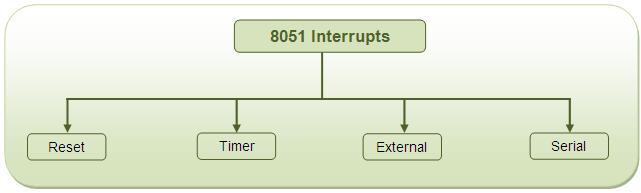
Introduction
An interrupt is an external or internal event that interrupts the microcontroller to inform it that a device needs its service.
Why we need interrupt? – A single microcontroller can serve several devices by two ways
Interrupt
Whenever any device needs its service, the device notifies the microcontroller by sending it an interrupt signal. Upon receiving an interrupt signal, the microcontroller interrupts whatever it is doing and serves the device. The program which is associated with the interrupt is called the interrupt service routine (ISR) or interrupt handler
Polling
The microcontroller continuously monitors the status of a given device. When the conditions met, it performs the service. After that, it moves on to monitor the next device until every one is serviced
Advantage of interrupt
The polling method is not efficient, since it wastes much of the microcontroller’s time by polling devices that do not need service. The advantage of interrupts is that the microcontroller can serve many devices, Each devices can get the attention of the microcontroller based on the assigned priority . For the polling method, it is not possible to assign priority since it checks all devices in a round-robin fashion.
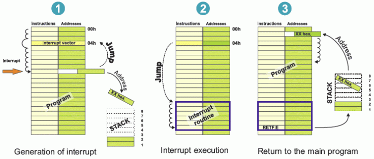
Interrupt works process
- Whenever any device needs its service, the device notifies the microcontroller by sending it an interrupt signal.
- Upon receiving an interrupt signal, the microcontroller interrupts whatever it is doing and saves the address of the next instruction (PC) on the stack pointer (SP).
- It jumps to a fixed location in memory, called the interrupt vector table, that holds the address of the ISR(interrupt service routine). Each interrupt has its own ISR. The microcontroller gets the address of the ISR from the interrupt vector table and jumps to it
- It starts to execute the interrupt service subroutine until it reaches the last instruction of the subroutine which is RETI (return from interrupt).RETI not used in C coding.
- Upon executing the RETI instruction, the microcontroller returns to the place where it was interrupted and First, it gets the program counter (PC) address from the stack pointer by popping the top two bytes of the stack into the PC
- Then it starts to execute from that address and continue what it executing before.
- This whole process is shown graphically in above pics.
Vector Address: This is the address where controller jumps after the interrupt to serve the ISR (interrupt service routine).
| Interrupt | Flag | Interrupt vector address |
|---|---|---|
| Reset | – | 0000H |
| INT0 (Ext. int. 0) | IE0 | 0003H |
| Timer 0 | TF0 | 000BH |
| INT1 (Ext. int. 1) | IE1 | 0013H |
| Timer 1 | TF1 | 001BH |
| Serial | TI/RI | 0023H |
Reset
A reset can be considered to be the ultimate interrupt because it is non maskable interrupt mean it can not avoid when it is called, since no combination of bits in any register can stop, or mask the reset action, unlike other interrupts. RESET is actually external switch Whenever a high level is applied to the RST pin, the 8051 enters a reset condition and program will restart from address 0x0000.
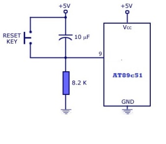
After the RST pin is brought low, the internal registers will have their initial value from where it start system.
In simple word, RESET does the work like rebooting system.
Internal interrupt (Timer Interrupt)
8051 has two internal interrupts namely timer0 and timer1. Whenever timer overflows, timer overflow flags (TF0/TF1) are set. Then the microcontroller jumps to their vector address to serve the interrupt. For this, global and timer interrupt should be enabled.
Serial interrupt
8051 has serial communication port and have related serial interrupt flags (TI/RI). When the last bit (stop bit) of a byte is transmitted, TI serial interrupt flag is set and when last bit (stop bit) of receiving data byte is received, RI flag get set.
IE register: Interrupt Enable Register
IE register is used to enable/disable interrupt sources.

Bit 7 – EA: Enable All Bit
1 = Enable all interrupts
0 = Disable all interrupts
Bit 6,5 – Reserved bits
Bit 4 – ES: Enable Serial Interrupt Bit
1 = Enable serial interrupt
0 = Disable serial interrupt
Bit 3 – ET1: Enable Timer1 Interrupt Bit
1 = Enable Timer1 interrupt
0 = Disable Timer1 interrupt
Bit 2 – EX1: Enable External1 Interrupt Bit
1 = Enable External1 interrupt
0 = Disable External1 interrupt
Bit 1 – ET0: Enable Timer0 Interrupt Bit
1 = Enable Timer0 interrupt
0 = Disable Timer0 interrupt
Bit 0 – EX0: Enable External0 Interrupt Bit
1 = Enable External0 interrupt
0 = Disable External0 interrupt
Interrupt priority
Priority to the interrupt can be assigned by using interrupt priority register (IP)
Interrupt priority after Reset:
| Priority | Interrupt source | Intr. bit / flag |
|---|---|---|
| 1 | External Interrupt 0 | INT0 |
| 2 | Timer Interrupt 0 | TF0 |
| 3 | External Interrupt 1 | INT1 |
| 4 | Timer Interrupt 1 | TF1 |
| 5 | Serial interrupt | (TI/RI) |
In the table, interrupts priorities upon reset are shown. As per 8051 interrupt priorities, lowest priority interrupts are not served until microcontroller is finished with higher priority ones. In a case when two or more interrupts arrives microcontroller queues them according to priority.
IP Register: Interrupt priority register
8051 has interrupt priority register to assign priority to interrupts.

Bit 7,6,5 – Reserved bits.
Bit 4 – PS: Serial Interrupt Priority Bit
1 = Assign high priority to serial interrupt.
0 = Assign low priority to serial interrupt.
Bit 3 – PT1: Timer1 Interrupt Priority Bit
1 = Assign high priority to Timer1 interrupt.
0 = Assign low priority to Timer1 interrupt.
Bit 2 – PX1: External Interrupt 1 Priority Bit
1 = Assign high priority to External1 interrupt.
0 = Assign low priority to External1 interrupt.
Bit 1 – PT0: Timer0 Interrupt Priority Bit
1 = Assign high priority to Timer0 interrupt.
0 = Assign low priority to Timer0 interrupt.
Bit 0 – PX0: External0 Interrupt Priority Bit
1 = Assign high priority to External0 interrupt.
0 = Assign low priority to External0 interrupt.
External interrupts in 8051
The external interrupts are the interrupts received from the (external) devices interfaced with the microcontroller. They are received at INTx pins of the controller. The 8051 has two external hardware interrupts PIN 12 (P3.2) and Pin 13 (P3.3) of the 8051, designated as INT0 and INT1 are used as external hardware interrupts. Upon activation of these pins, the 8051 gets interrupts in what ever it is doing and jumps to the vector table to perform the interrupt service routine(ISR).
In polling method microcontroller has to continuously check for a pulse by monitoring pin, whereas, in interrupt method, the microcontroller does not need to poll. Whenever an interrupt occurs microcontroller serves the interrupt request.
External interrupt has two types of activation level
- Edge triggered (Interrupt occur on rising/falling edge detection)
- Level triggered (Interrupt occur on high/low-level detection)
In 8051, two types of activation level are used. These are,
Low level triggered
Whenever a low level is detected on the INT0/INT1 pin while global and external interrupts are enabled, the controller jumps to interrupt service routine (ISR) to serve interrupt.
Falling edge triggered
Whenever falling edge is detected on the INT0/INT1 pin while global and ext. interrupts are enabled, the controller jumps to interrupt service routine (ISR) to serve interrupt.
There are lower four flag bits in TCON register required to select and monitor the external interrupt type and ISR status.
TCON: Timer/ counter Register

Bit 3- IE1:
External Interrupt 1 edge flag, set by hardware when interrupt on INT1 pin occurred and cleared by hardware when interrupt get processed.
Bit 2- IT1:
This bit selects external interrupt event type on INT1 pin,
1= sets interrupt on falling edge
0= sets interrupt on low level
Bit 1- IE0:
Interrupt0 edge flag, set by hardware when interrupt on INT0 pin occurred and cleared by hardware when an interrupt is processed.
Bit 0 – IT0:
This bit selects external interrupt event type on INT0 pin.
1= sets interrupt on falling edge
0= sets interrupt on low level
Program Of external interrupts of 8051 , In Which Interrupt 0 control 7 Segment And Interrupt 1 Control LCD Display
The external interrupts are the interrupts received from the (external) devices interfaced with the microcontroller. They are received at INTx pins of the controller. These can be level triggered or edge triggered. In level triggered, interrupt is enabled for a low at INTx pin; while in case of edge triggering, interrupt is enabled for a high to low transition at INTx pin. The edge or level trigger is decided by the TCON register. The TCON register has following bits:
#include<reg51.h>
sfr seven_seg=0x80; // 7segment at port 0
sfr led=0xa0; // led at port 2
sfr lcd=0x90; // data of lcd at port 1
sbit rs=P3^5; // rs pin at P3.5
sbit rw=P3^6; // rw pin at P3.6
sbit en=P3^7; // en pin at P3.7
void delay(); // delay function
void cmd();
void display();
void main()
{
int data1[]={0xc0,0xf9,0xa4,0xb0,0x99,0x92,0x82,0xf8,0x80,0x90};
int i,j;
IE=0x85; // extrnal interrupt are enabled
while(1)
{
if(i==10)
i=0;
seven_seg=data1[i];
delay();
delay();
delay();
i++;
}
}
void led_control() interrupt 0 // interrupt(INT0) 0
{
led=0x00;
delay();
led=0xff;
delay();
}
void lcd_control() interrupt 4 // interrupt(INT1) 1
{
lcd=0x38;
cmd();
lcd=0x0e;
cmd();
lcd=0x01;
cmd();
lcd=0x06;
cmd();
lcd=0x80;
cmd();
lcd='W';
display();
lcd='E';
display();
lcd='L';
display();
lcd='C';
display();
lcd='O';
display();
lcd='M';
display();
lcd='E';
display();
lcd=' ';
display();
lcd='T';
display();
lcd='O';
display();
lcd=0xc0;
cmd();
lcd='W';
display();
lcd='O';
display();
lcd='R';
display();
lcd='L';
display();
lcd='D';
display();

}

void delay() // delay function
{
unsigned int i,j;
for(i=0;i<100;i++)
for(j=0;j<153;j++);
}
void cmd()
{
unsigned char i;
rs=0;
rw=0;
en=1;
for(i=0;i<2;i++);
en=0;
delay();
}
void display()
{
unsigned char i;
rs=1;
rw=0;
en=1;
for(i=0;i<2;i++);
en=0;
delay();
}
Programm of Serial Communication interrupt in which data send from PC is displayed on LCD
- Enable the Serial Interrupt (configure the IE register).
- Configure SCON register.
- Write routine or function for the Serial Interrupt. The interrupt number is 4.
- Clear the RI or TI flag within the routine.
#include<reg51.h>
sfr lcd=0xa0; // data of lcd at port 2
sbit rs=P3^5; // rs pin at P3.5
sbit rw=P3^6; // rw pin at P3.6
sbit en=P3^7; // en pin at P3.7
void delay(); // for delay
void cmd(); // lcd in command mode
void display(); // lcd is in display mode
char serial_receive(); // initialize controller as serial communication
void serial_initialize(); // receive data to controller
void serial_transmit(unsigned char x); // transmit data to computer
unsigned rec; // gloable variable
void main()
{
int x=0;
serial_initialize(); // call the initialize function
// initialization of lcd
lcd=0x38;
cmd();
lcd=0x0e;
cmd();
lcd=0x01;
cmd();
lcd=0x06;
cmd();
lcd=0x80;
cmd();
while(1);
}
void serial_interrupt() interrupt 4
{
if(RI==1)
{
rec=serial_receive();
lcd=rec;
display();
}
}
void serial_initialize()
{
TMOD=0x20; //timer 1 in mode2 (8-bit auto-reload) to set baud rate
TH1=0xfd; //  baud rate of 9600hz , crystal oscillator =11.0592Mhz
SCON=0x50;
//make SM0=0 and SM1=1 present in SCON register,
//so that we select, Serial Mode 1, 8-bit data,1 stop bit, 1 start bit
// make REN=1 present in SCON register , receive data on RxD pin
TR1=1; // to start timer
IE=0X90; // to make serial interrupt interrupt enable
}
char serial_receive()
{
// RI bit is present in SCON register
while(RI==0); // wait untill hole 8 bit data is received completely.
rec=SBUF; // data is received in SBUF register
RI=0; // make RI bit to 0 so that next data is received
return rec; // return rec where funtion is called
}
void serial_transmit(unsigned char x)
{
SBUF=x; //data is put in SBUF register present in controller to transmit
// TI bit is present in SCON register
while(TI==0); // wait untill TX is compleated.
TI=0; // make TI bit to zero for next transmittion
}
void cmd()
{
unsigned char i;
rs=0;
rw=0;
en=1;
for(i=0;i<2;i++);
en=0;
delay();
}
void display()
{
unsigned char i;
rs=1;
rw=0;
en=1;
for(i=0;i<2;i++);
en=0;
delay();
}
void delay()
{
unsigned int i,j;
for(i=0;i<100;i++)
for(j=0;j<153;j++);
}
Program of Timer 0 Interrupt in which LED Blinking is Controlled
- Configure TMOD register to select timer(s) and its/their mode.
- Load initial values in THx and TLx for mode 0 and 1; or in THx only for mode
- Enable Timer Interrupt by configuring bits of IE register.
- Start timer by setting timer run bit TRx.
- Write subroutine for Timer Interrupt. The interrupt number is 1 for Timer0 and 3 for Timer1.
- Note that it is not required to clear timer flag TFx.
- To stop the timer, clear TRx in the end of subroutine. Otherwise it will restart from 0000H in case of modes 0 or 1 and from initial values in case of mode 2.
- If the Timer has to run again and again, it is required to reload initial values within the routine itself (in case of mode 0 and 1). Otherwise after one cycle timer will start counting from 0000H.
#include<reg51.h>
sfr led=0x90;
void main()
{
TMOD=0X01; // MODE 1 OF TIMER O IS SELECTED
TL0=0X00;
TH0=0X00;
IE=0X82;
TR0=1;
led=0x00;
while(1);
}
void timer_0() interrupt 1
{
led=~led; // toggle the port 1
}
Circuit Diagram
Circuit diagram of external interrupts of 8051 , In Which Interrupt 0 control 7 Segment And Interrupt 1 Control LCD Display
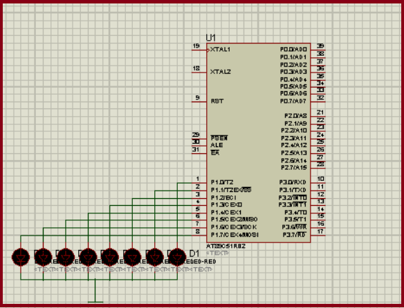
Circuit diagram of Timer 0 Interrupt in which LED Blinking is Controlled
Application of interrupt
To provide services to the devices efficiently.

Leave a comment