
What is serial COM ?
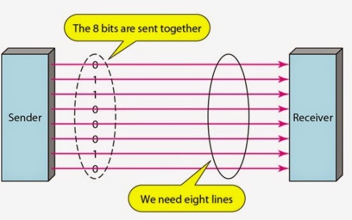
Microcontrollers can communicate data in either parallel form or serial form. In parallel communication, data is transferred over more than one wire for example if 8 wires of one microcontroller are connected to any other peripheral device or another microcontroller then at a particular time 8 data bits are transferred. On the other hand in serial communication, data is transferred in bit by bit manner over a single wire. For example if a microcontroller 1 is transferring data to another microcontroller 2 in serial form then TXD pin of microcontroller 1 will be connected to RXD pin of microcontroller 2 and data is transferred from microcontroller 1 to microcontroller 2 in bit by bit manner over a single wire. If microcontroller 2 wants to send some data to microcontroller 1 then for that TXD pin of microcontroller 2 must be connected to RXD pin of microcontroller 1 and again data bits will be transferred over a single wire. So it is clear that for full duplex communication of data two wires are involved and for simplex communication only one wire will be involved.
Parallel communication requires more number of wires than serial communication but it has higher speed of data transfer as more than one bit is transferred at a given time. Serial communication is preferred when the distance b/w transmitter and receiver is large and it is required to save the cabling cost and reduce h/w complexity but definitely this comes at the cost of reduced speed of data transfer.
Parallel data transmission
Serial data transmission
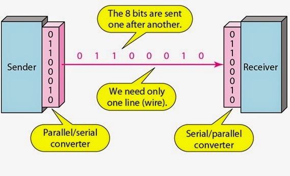
In serial communication parallel to serial converter and serial to parallel converter module is required. In 8051 in built UART (Universal Asynchronous Receiver Transmitter) module performs the job of serial communication of data.
Data communication process can be synchronous or asynchronous. The following points clearly discriminates between these two modes of data transfer-
About & Types serial COM
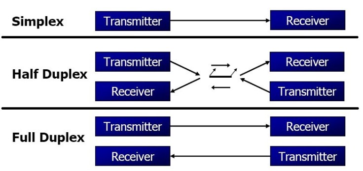
- If data transmitted one way a time, it is referred to as half duplex.
- If data can go both ways at a time, it is full duplex.
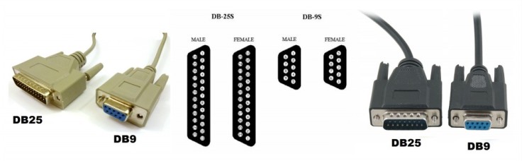
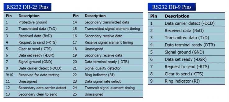
Following are the pin connectors that are used to connect microcontroller with PCs.
Serial data communication uses two methods:
- Synchronous method transfers a block of data at a time
- Asynchronous method transfers a single byte at a time
Synchronous data transfer
sender and receiver use the same clock signal
- supports high data transfer rate
- needs clock signal between the sender and the receiver
- requires master/slave configuration
Asynchronous data transfer
Asynchronous serial data communication is widely used for character-oriented transmissions
- Each character is placed in between start and stop bits, this is called framing (8-bit = single character)
- Block-oriented data transfers use the synchronous method
- The start bit is always one bit, but the stop bit can be one or two bits. Due to the extended ASCII Characters, 8-bit ASCII data is common. In modern PCs, the use of one stop bit is standard. Assuming that we are transferring a text file of ASCII characters using 1 stop bit, we have a total of 10 bits for each character including 8 character with 1 start and 1 stop bit.
- The rate of data transfer in serial data communication is stated in bps (bits per second). Another widely used terminology for bps is baud rate. It is modem terminology and is defined as the number of signal changes per second. In modems, there are occasions when a single change of signal transfers several bits of data.
- The data transfer rate of given computer system depends on communication ports incorporated into that system
- IBM PC/XT could transfer data at the rate of 100 to 9600 bps
- Pentium-based PCs transfer data at rates as high as 56Kbps
- In asynchronous serial data communication, the baud rate is limited to 100Kbps.
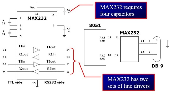
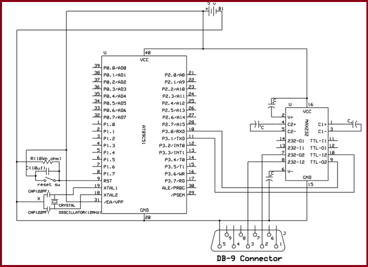
- Microcontroller used CMOS logics generally, so we need a line driver such as the MAX232 chip which is required to convert RS232 voltage levels to CMOS levels, and vice versa.
- Following diagram is shown interfacing diagram of 8051 with PC and use of MAX232 IC.
Data Transfer
In 8051 microcontroller serial communication of data is performed with the help of following special purpose registers-
- SBUF (Serial buffer register)
- SCON (serial control register)
- TMOD (Timer mode register)
- TCON (Timer control register)
- TH1 (Timer1 register higher byte)
Before going further it is extremely important to first understand these registers and their importance with reference to serial communication.
SBUF (Serial buffer register)
It is an 8-bit register and is used for serial communication of data in 8051 microcontroller. Whatever data is required to be transmitted via TXD line must be placed in the SBUF register. Similarly the received data via RXD line is saved in SBUF register. When data is written to SBUF register then it is framed in b/w start and stop bit before it is transmitted via TXD line and similarly during reception of data start and stop bits are removed and actual data bits are extracted from the received frame and then it is placed in the SBUF register.
SCON (Serial control register)
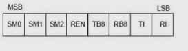
SM0, SM1 Serial port mode specifier
REN (Receive enable) set/cleared by software to enable/disable reception.
TI Transmit interrupt flag.
RI Receive interrupt flag.
SM2 = TB8 = RB8 =0 (not widely used)
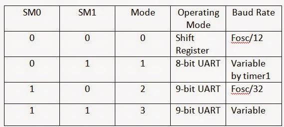
SM1 and SM0 determine the framing of data.
Only mode 1 is compatible with COM port of PC.
TMOD (Timer mode register)
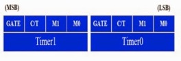
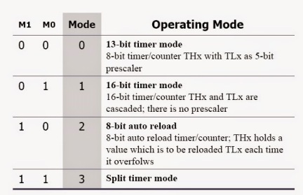
Both timer 0 and timer 1 use the same register, called TMOD, to set the various timer modes. TMOD is an 8-bit register in which the lower 4-bits are set aside for timer 0 and the upper 4-bits are set aside for timer 1. In each case, the lower 2 bits are used to set the timer mode and the upper two bits are used to specify the operation.
C/T
If this bit is set then counter operation is performed (for counting applications) and if this bit is clear then timer operation is performed (for delay generation ). The clock source for timer is the crystal oscillator that is connected to the 8051 micro-controller. Crystal oscillator also determines the speed at which the timer ticks.
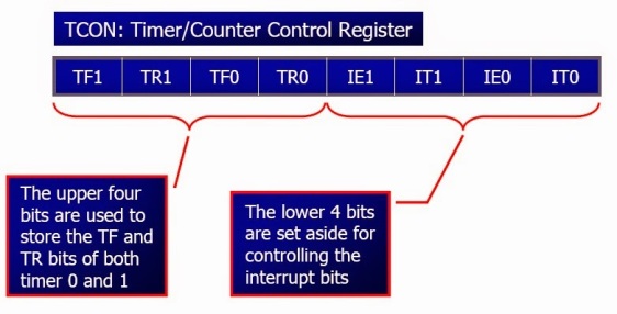
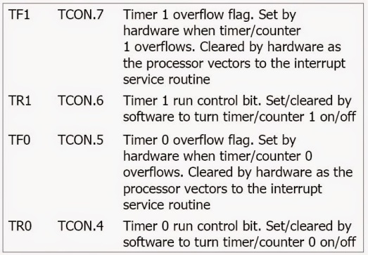
TCON (Timer Control Register)
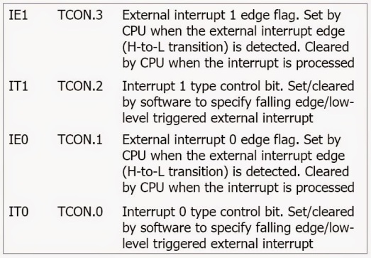
TH1 (Timer 1 register high byte)
Timer 1 high byte register is loaded with appropriate value for baud rate generation. Timer 1 in mode 2 is used for baud rate generation.
Concept of Baud Rate Generation in 8051 Micro-controller
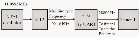
8051 divides the crystal oscillator frequency by 12 to get the machine cycle frequency. UART divides the machine cycle frequency by 32 and sends it to Timer 1 to set the baud rate.
Timer 1, mode 2 (8-bit, auto-reload)
Define TH1 to set the baud rate.
XTAL = 11.0592 MHz
The system frequency = 11.0592 MHz / 12 = 921.6 kHz
Timer 1 has 921.6 kHz/ 32 = 28,800 Hz as source
Baud rate = 28,800/3= 9,600 bps
So TH1 must be loaded with value of FDH (-3) for the generation of baud rate of 9600 bps.
For the crystal oscillator frequency of 11.0592MHz the below given table can be used as a reference for getting the value that is required to be loaded into TH1 register for the desired baud rate generation.
| Baud Rate | TH1 (Decimal) | TH1 (Hex) |
| 9600 | -3 | FD |
| 4800 | -6 | FA |
| 2400 | -12 | F4 |
| 1200 | -24 | E8 |
What is the significance/Importance of TI and RI flags?
When 8051 is transmitting serial data then TI flag (Transmit Interrupt Flag) plays a very important role. This flag must be monitored to check whether data transfer operation is executed successfully or not. This bit is set by the hardware at the beginning of the stop bit in mode 1. This flag bit must be cleared by software. In embedded C the instructions that can be used to monitor the status of TI flag is-
SBUF = ’U’; // load SBUF with the data that is required to be transmitted
While (TI ==0); //stay on this line till TI=0 (wait until transmitted)
TI=0; // clear TI flag
Similarly during reception RI flag (Receive Interrupt Flag) plays a very important role. This flag must be monitored to check whether any data is received or not. This flag bit is set in half way through the stop bit in mode 1 and must be cleared by the software. The instructions that can be used to monitor the status of RI flag in embedded C are-
While (RI==0); // stay on this line till RI=0 (wait to receive)
temp = SBUF; //read SBUF and store it in some temp variable
P2 = temp; // put the received data on port 2
RI=0; // clear the RI flag
In simple terms TI = 1 indicates that data is transferred successfully and RI = 1 indicates that data byte is received successfully.
Circuit Diagram
code
#include<reg51.h>

char serial_receive(); // initialize controller for serial communication

void serial_initialize(); // receive data to controller via rxd pin

void serial_transmit(unsigned char x); // transmit data to computer
unsigned rec; // gloable variable

void delay(int x);

void main()
{
serial_initialize(); // call the initialize function
while(1)
{
serial_transmit('H'); // call transmit function
delay(10000); // calling of delay function
serial_transmit('E'); // call transmit function
delay(10000); // calling of delay function
serial_transmit('L'); // call transmit function
delay(10000); // calling of delay function
serial_transmit('L'); // call transmit function
delay(10000); // calling of delay function
serial_transmit('O'); // call transmit function
delay(10000); // calling of delay function
serial_transmit(0x0d); // call transmit function
delay(40000);
delay(40000);
}
}
void serial_initialize()
{
TMOD=0x20; //timer 1 in mode2 (8-bit auto-reload) to set baud rate
TH1=0xfd; //  baud rate of 9600hz , crystal oscillator =11.0592Mhz
SCON=0x50;
/*make SM0=0 and SM1=1 present in SCON register,
so that we select, Serial Mode 1, 8-bit data,1 stop bit, 1 start bitmake

 REN=1 present in SCON register ,it allows 8051 to receivn RxD pin*/
TR1=1; // to start timer
IE=0X90; // to make serial interrupt interrupt enable
}
char serial_receive()
{
/* RI bit is present in SCON register*/
while(RI==0); // wait untill8 bit data is received completely.

 RI 1 when reception is compleated
rec=SBUF; // data is received in SBUF register
RI=0; // make RI bit to 0 so that next data is received
return rec; // return rec where funtion is called
}
void serial_transmit(unsigned char x)
{
SBUF=x; // 8 Bit data is put in SBUF to transmit
// TI bit is present in SCON register
while(TI==0); // wait untill transmission is completed.
TI=0; // make TI bit to zero for next transmittion
}
void delay(int x)
{
int i;
for(i=0;i<x;i++);
}
Applications
As in modern computers, serial ports are not used anymore, but still they finds their application in Industries and Consumer products. Following are the main fields of application of Serial Port:
- Industrial Automation Systems
- Scientific Analysis
- GPS receivers
- LCD and Plasma monitors
- Uninterruptible power supply
- Older Mobile Phones
- Software debuggers
- Printers
- Networking
- Bar code scanners
- Modems
- Consumer Products etc.

Leave a comment