
Introduction-
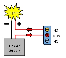
Relay is an electromagnetic switch, which is controlled by small current, and used to switch ON and OFF relatively much larger current. Means by applying small current we can switch ON the relay which allows much larger current to flow. A relay is a good example of controlling the AC (alternate current) devices, using a much smaller DC current. Commonly used Relay is Single Pole Double Throw (SPDT) Relay, it has five terminals as below:


When there is no voltage applied to the coil, COM (common) is connected to NC (normally closed contact). When there is some voltage applied to the coil, the electromagnetic field produced, which attracts the Armature (lever connected to spring), and COM and NO (normally open contact) gets connected, which allow a larger current to flow. Relays are available in many ratings, here we used 5V operating voltage relay, which allows 10A-250VAC current to flow.
The relay is always configured by using a small Driver circuit which consists a Transistor, Diode and a resistor. Transistor is used to amplify the current so that full current (from the DC source – 9v battery) can flow through a coil to fully energies it. The resistor is used to provide biasing to the transistor. And Diode is used to prevent reverse current flow, when the transistor is switched OFF. Every Inductor coil produces equal and opposite EMF when switched OFF suddenly, this may cause permanent damage to components, so Diode must be used to prevent reverse current. A Relay module is easily available in the market with all its Driver circuit on the board or you can create it on perf board or PCB like below. Here we have used 5V Relay module.
It helps microcontrollers (or microcontroller based boards) like Arduino to switch on or off different household appliances like motors, lights, water heaters, television and fans etc.
Today, Arduino is being used for a wide range of applications like controlling LEDs, monitoring temperature, logging data and turning on motors etc. Another important task that can be accomplished by the Arduino is controlling a 5V Relay to operate high voltage AC appliances and devices.
Arduino family of microcontrollers, like UNO, Nano and Mega etc. can be programmed to control a simple 5V relay i.e. switch it on or off on the event of pushing a button, reading the value of temperature from a thermistor or just by setting up a predefined timer.
Relay Module Type
There many types of relay modules available like 1 relay, 2 relay, 4 relay and 8 relay


- COM: common pin
- NC (Normally Closed): the normally closed configuration is used when you want the relay to be closed by default, meaning the current is flowing unless you send a signal from the Arduino to the relay module to open the circuit and stop the current.
- NO (Normally Open): the normally open configuration works the other way around: the relay is always open, so the circuit is broken unless you send a signal from the Arduino to close the circuit.
Components Required:
- Arduino
- 5v relay
- AC appliance or Bulb
- BC547 transistor
- 1k resistor
- Breadboard or PCB
- Connecting jumper wire
- Power supply
- 1n4007 diode
- Screw terminal or terminal block
Single Relay Circuit-
For the DC part of the circuit:
Arduino digital pin 10 –> module pin S
Arduino GND –> module pin –
Arduino +5V –> module pin +
Circuit for Relay Module-
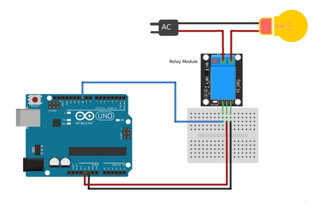
AC Part of the circuit:
On the AC side connect your feed to Common (middle contact) and use NO (Normally Open) to Lamp. It will get power when (S) is high.
Warning: Always be very careful when experimenting with AC, electrical shock can result in serious injures.Relay module from bottom side is open when AC is connected do not touch the circuit.
Code-
/*
Author:-Dharmendra Kumar Yadav
*/
int relay = 10; // relay turns trigger signal - active high;
void setup ()
{
pinMode (relay, OUTPUT); // Define port attribute is output;
}
void loop ()
{
digitalWrite (relay, HIGH); // relay conduction;
delay (1000);
digitalWrite (relay, LOW); // relay switch is turned off;
delay (1000);
}
2 Channel Relay Module-
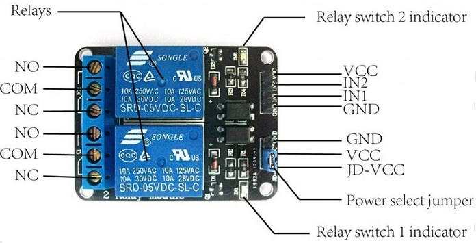
The connections between the relay module and the Arduino are really simple:
- GND: goes to ground
- IN1: controls the first relay (it will be connected to an Arduino digital pin)
- IN2: controls the second relay (it should be connected to an Arduino digital pin if you are using this second relay. Otherwise, you don’t need to connect it)
- VCC: goes to 5V
Code-
/*
Author:-Dharmendra Kumar Yadav
*/
int relay1 = 10; // relay1 turns trigger signal - active high;
int relay2 = 11; // relay2 turns trigger signal - active high;
void setup ()
{
pinMode (relay1, OUTPUT); // Define port attribute is output;
pinMode (relay2, OUTPUT); // Define port attribute is output;
}
void loop ()
{
digitalWrite (relay1, HIGH); // relay1 conduction;
digitalWrite (relay2, HIGH); // relay2 conduction;
delay (1000);
digitalWrite (relay1, LOW); // relay1 switch is turned off;
digitalWrite (relay2, HIGH); // relay switch is turned off;
delay (1000);
}
4 Channel Relay Module-
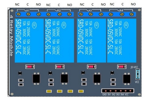
- Logic GND: This will be connected to GND on your Arduino.
- Input 1 (IN 1): This will be connected to digital pin on your Arduino, or leave it unconnected if you do not want to use this channel.
- Input 2 (IN 2): This will be connected to the digital pin on your Arduino, or leave it unconnected if you do not want to use this channel.
- Input 3 (IN 3): This will be connected to the digital pin on your Arduino, or leave it unconnected if you do not want to use this channel.
- Input 4 (IN 4): This will be connected to the digital pin on your Arduino, or leave it unconnected if you do not want to use this channel.
- Logic VCC: This will be connected to the 5v pin of the Arduino o power the 4 relay module.
- You can also power the 4 relay module using the external power but make sure both ground are common.
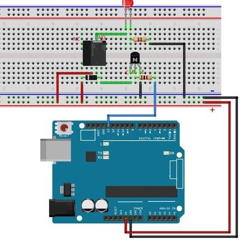
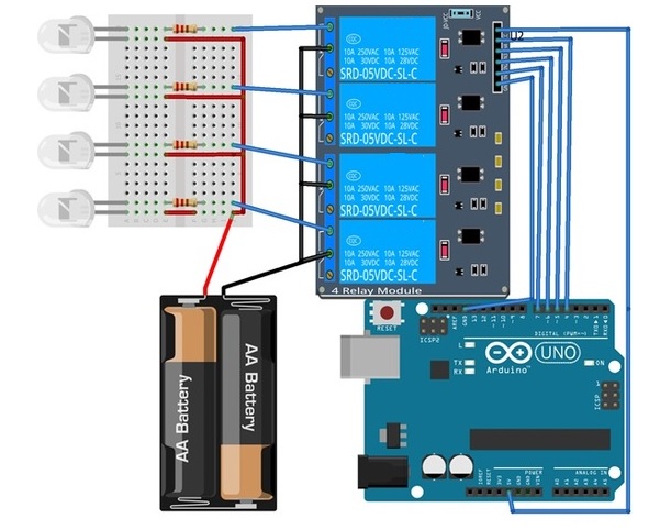
4 relay module interfacing with arduino-
The connection of 4 relay module to an Arduino is very easy and allows you to control many devices through Arduino (both A.C and D.C). In this example we will connect a simple load such as a led at the output of the relay and will control it by using the Arduino. First connect the 5v of the Arduino to the VCC of the 4 relay module and the ground of the Arduino to the ground of the 4 relay module. Then we will have to connect the communication pins IN1, IN2, IN3, and IN4 to the Arduino data pins 7, 6, 5, and 4.
We will use a 3v battery to power the Led’s. So we have connected the positive of the battery to the positive side of the led’s and then we have connected the negative side to the com of each relay and the NO to the negative side of the led’s.
Components Required for relay module
Code-
/*

Author:-Dharmendra Kumar Yadav
*/
int relay1_pin = 4;
int relay2_pin = 5;
int relay3_pin = 6;
int relay4_pin = 7;
void setup() {
pinMode(relay1_pin, OUTPUT);
pinMode(relay2_pin, OUTPUT);
pinMode(relay3_pin, OUTPUT);
pinMode(relay4_pin, OUTPUT);
digitalWrite(relay1_pin, LOW);
digitalWrite(relay2_pin, LOW);
digitalWrite(relay3_pin, LOW);
digitalWrite(relay4_pin, LOW);
}
void loop() {
digitalWrite(relay1_pin, HIGH);
delay(1000);
digitalWrite(relay2_pin, HIGH);
delay(1000);
digitalWrite(relay3_pin, HIGH);
delay(1000);
digitalWrite(relay4_pin, HIGH);
delay(1000);

digitalWrite(relay4_pin, LOW);
delay(1000);
digitalWrite(relay3_pin, LOW);
delay(1000);
digitalWrite(relay2_pin, LOW);
delay(1000);
digitalWrite(relay1_pin, LOW);
delay(1000);
}
Advantages and Disadvantages
Advantages: The main and important advantage of connecting a 5V relay with Arduino is that it can be powered by Arduino itself.
Disadvantages: A transistor based relay might not be ideal for long time use as there will always be noise in the relay coil. A suitable option will be using additional isolation like an opto-isolator or completely eliminating the electromechanical relay and replacing it with solid state relay.
Applications
- Interfacing a 5V Relay with Arduino opens up the door to a huge number of applications. Although the main task of the relay is to control a load, how that relay is being operated by the Arduino makes it an interesting project.
- Some of the techniques and methods using which we can control the relay are: Bluetooth, Infrared (IR) remote, RF Transmitter – Receiver Pair or even using Internet.
- Arduino based Home Automation requires the combination of Arduino and many relay module (depending on the number of loads).

Leave a comment