
Introduction-
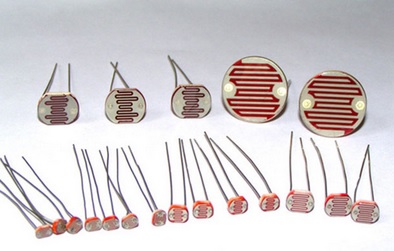
LDR is Light Dependent Resistor. LDRs are made from semiconductor materials to enable them to have their light-sensitive properties. There are many types but one material is popular and it is cadmium sulfide (CdS). These LDRs or PHOTO RESISTORS works on the principle of “Photo Conductivity”. Now what this principle says is, whenever light falls on the surface of the LDR (in this case) the conductance of the element increases or in other words, the resistance of the LDR falls when the light falls on the surface of the LDR. This property of the decrease in resistance for the LDR is achieved because it is a property of semiconductor material used on the surface.
we are going to control the light based of darkness outside, the light turns ON automatically when it is dark outside and turns off when it gets bright. For this, we need a light sensor to detect the light condition and some circuitry to control the Light sensor. It’s like Dark and light Detector circuit but this time we are using Arduino to get more control over light.
Material Required-
- Arduino UNO
- LDR (Light Dependent Resistor)
- Resistor (100k-1;330ohm-1)
- LED – 1
- Relay module – 5v
- Bulb/CFL
- Connecting wires
- Breadboard
Working of LDR
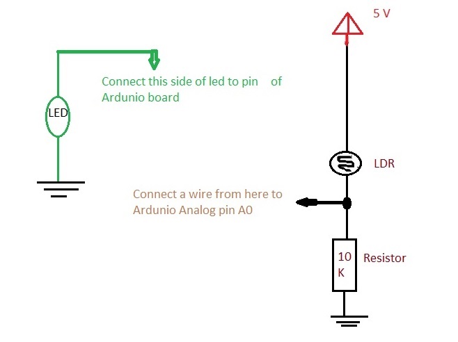
You may wonder why you’re unable to hook the LDR straight from the +5V pin to the A0 pin. While the LDR’s resistance does change, you don’t have a voltage divider in this setup. Whether resistance is relatively high or low, it’s all “seen” across the LDR component, fixing A0 at +5V. When you add the resistor to ground, it forms a voltage divider. Now the LDR must “spread” the voltage across the two resistors in series, and A0 senses the middle value.
The equation at work here is:

To see what happens without a voltage divider, pull the ground pin out of the circuit board temporarily. You’ll see the serial monitor number jump up to 1023, indicating that the full 5V of potential is set at that pin.
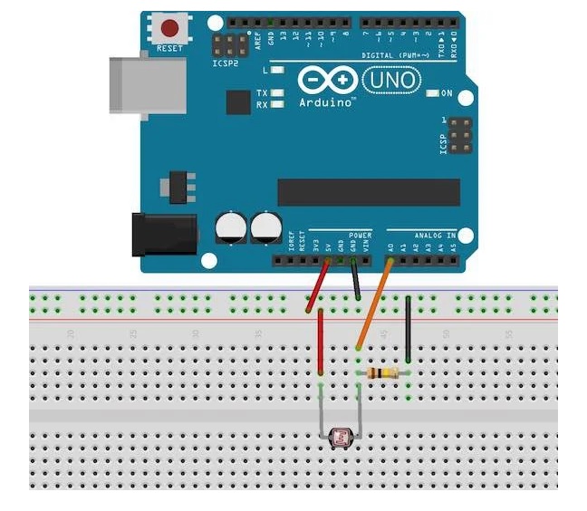
1.Test the LDR Sensor
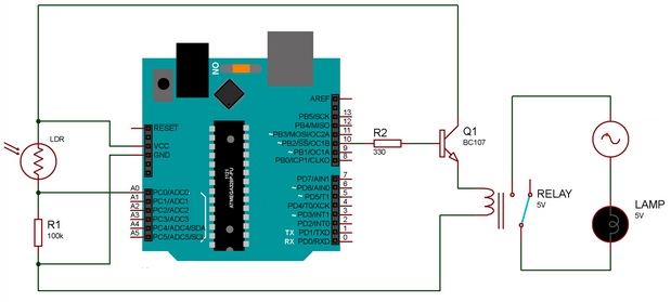
As per the circuit diagram, we have made a voltage divider circuit using LDR and 100k resistor. The voltage divider output is feed to the analog pin of the Arduino. The analog Pin senses the voltage and gives some analog value to Arduino. The analog value changes according to the resistance of LDR. So, as the light falls on the LDR the resistance of it get decreased and hence the voltage value increase.
Intensity of light ↓ – Resistance↑ – Voltage at analog pin↓
Circuit Diagram-
Code-
After connecting the LDR to your Arduino, you can check for the values coming from the LDR via the Arduino. To do this, connect the Arduino via USB to your PC and open up the Arduino IDE or software. Next, paste this code and upload it to your Arduino:
/*Author:Dharmendra Kumar yadav*/
int sensorPin = A0; // select the input pin for LDR

int sensorValue = 0; // variable to store the value coming from the sensor
void setup() {
Serial.begin(9600); //sets serial port for communication
}
void loop() {
sensorValue = analogRead(sensorPin); // read the value from the sensor
Serial.println(sensorValue); //prints the values coming from the sensor on the screen
delay(100);
}
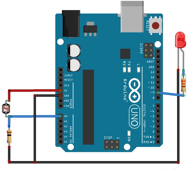
2.Working of LDR controlled LED using Arduino
Arduino can adjust the intensity of an LED in response to the ambient light detected by a LDR. You can build this device in a few steps:
Circuit-
Code-
/*
Author :Dharmendra Kumar Yadav
*/
int LED = 0;
int LDR = A0;

void setup()
{
Serial.begin(9600);
pinMode(LED, OUTPUT);
pinMode(LDR, INPUT);
}

void loop() {
int LDRValue = analogRead(LDR);
Serial.print("sensor = ");
Serial.print(LDRValue);

if (LDRValue <=700)
{
digitalWrite(LED, HIGH);
Serial.println("It's Dark Outside; Lights status: ON");
}
else
{
digitalWrite(LED, LOW);
Serial.println("It's Bright Outside; Lights status: OFF");
}
}
3.Controlling Relay using LDR with Arduino
Instead of controlling an LED according to the brightness and darkness, we can control our home lights or any electrical equipment. All we have to do is connect a relay module and set the parameter to turn ON and OFF the any AC appliance according to the intensity of the light. If the value falls below 600, which means it Dark, then the relay operates and the lights turns ON. If the value is greater than 600, which means its day or bright, then the relay will not operate and the lights remain OFF
Circuit-
Code-
/*
Author :Dharmendra Kumar Yadav
*/

#define relay 10
int LDR = A0;

void setup()
{
Serial.begin(9600);
pinMode(relay, OUTPUT);
pinMode(LDR, INPUT);
}

void loop() {
int LDRValue = analogRead(LDR);
Serial.print("sensor = ");
Serial.print(LDRValue);

if (LDRValue <=600)
{
digitalWrite(relay, HIGH);
Serial.println("It's Night Time; Lights status: ON");
}
else
{
digitalWrite(relay, LOW);
Serial.println("It's Day Time; Lights status: OFF");
That’s All for Today!

Leave a comment