
Introduction
A diode is a component that lets current flow in one direction and blocks it from flowing in the other direction. It has two pins; anode and cathode.
The diode symbol looks like an arrow pointing toward a line. The line represents the cathode side, and so does the line marking on the diode component itself.

How To Connect A Diode in a Circuit?
A diode will block or let current flow, depending on how you connect it in a circuit. Below you can see an example circuit.

In the circuit above the diode is connected in the right direction. This means current can flow through it so that the Light-emitting diode (LED) will light up.
But what happens if we connect it the other way around?
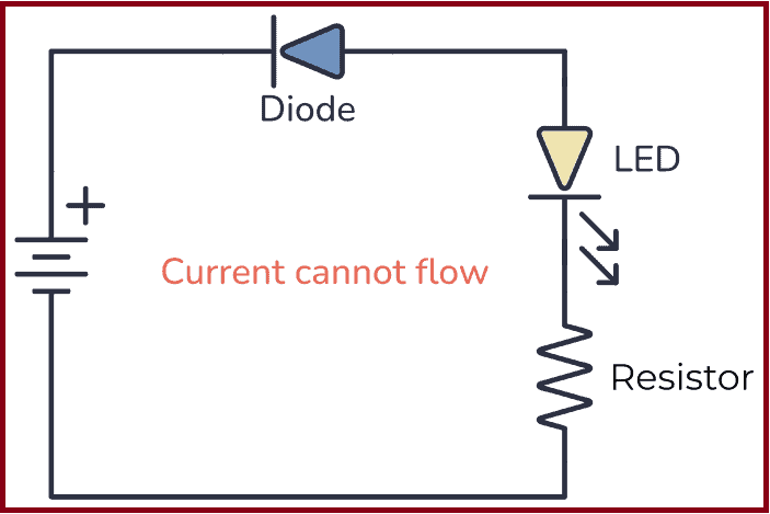
In this second circuit, the diode is connected the wrong way. This means that no current will flow in the circuit and the LED will be turned OFF.
What Is a Diode Used For?
A standard diode can be used for a range of things, from creating sound effects to power supplies. Below, you can see a few circuit examples with an explanation of what the diode is used for:
Sound Effects Clipping: By placing two diodes in parallel in opposite directions, you can get a clipping effect which creates an overdrive sound effect, often used in guitar pedals.

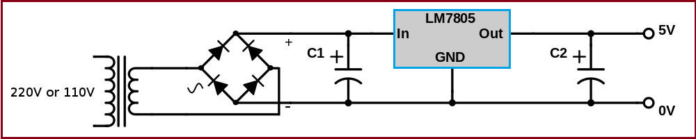
Converting from AC to DC: Sometimes diodes are used to convert from AC to DC by placing four rectifier diodes to create a bridge rectifier. This is often used after a transformer in a power supply, followed by a voltage regulator.
Protecting from voltage spikes: Components like motors and relays are basically inductors, which means their current will try to keep on flowing after the power is shut off. Diodes are used to safely discharge them.

How a Diode Works
The diode is created from a PN junction. You get a PN junction by taking a negatively doped and positively doped semiconductor material and putting it together.

At the intersection of these two materials, a depletion region appears. This depletion region acts as an insulator and refuses to let any current pass.
When you apply a positive voltage from the positive side to the negative side, the depletion layer between the two materials disappears and the current can flow from the positive to the negative side.
When you apply a voltage in the other direction, from the negative to the positive side, the depletion region expands and resists any current flowing.
How To Test Diodes With a Multimeter
You can test diodes with a multimeter to find the forward voltage. To test your diode, you need a multimeter with a diode function. If you see a diode symbol on your multimeter, that’s most likely your diode function.
- Connect the positive test lead to the diode’s anode.
- Connect the negative test lead to the diode’s cathode.
- The multimeter display will show you the forward voltage of your diode.
Things To Note About Diodes
- You have to apply enough voltage in the “right” direction – from positive to negative – for the diode to start conducting. Usually, this voltage is around 0.7 V to 1 V.
- It has limits and cannot conduct unlimited amounts of current.
- Diodes are not perfect components. If you apply voltage in the wrong direction, there will be a little bit of current flowing. This current is called leakage current.
- If you apply a high enough voltage in the “wrong” direction, the diode will break down and let current pass in this direction too.
Types of Diodes
There are many different types of diodes. The most common ones are:
- Signal diode
- Rectifier diode
- Zener diode
- Light-Emitting Diodes (LED)
- Schottky Diode
- Photodiode
- PIN diode
Signal and rectifier diodes are pretty much the same things except that rectifier diodes are built to handle more power.
Zener diodes are diodes that make use of the breakdown voltage when applying voltage the “wrong” way. They act as very stable voltage references.
Schottky Diodes have a lower forward voltage drop and faster switching speeds than standard signal diodes.
Photodiodes are diodes that are sensitive to light. They let current flow through them when exposed to light.
Light-Emitting Diodes (LED) are components that light up when current flows through them.
The Most Standard Diodes
Rectifier Diode
The rectifier diode is typically used for rectifying alternating current (AC) to direct current (DC). They can usually handle big currents and voltages. Sometimes referred to as power diodes.
Signal Diode
The signal diode works the same way as the rectifier diode. But it can only handle small currents and voltages. It is faster than the rectifier diode and is sometimes referred to as a high-speed diode.
The most typical signal diode is the 1N4148.
Zener Diode
The Zener diode is a component that will become very conductive (meaning that it will allow lots of current) for a certain voltage. This voltage is called the Zener voltage.
What this means is that the voltage drop over the Zener diode will not exceed the Zener voltage. The Zener diode is often used as a stable voltage reference.
Other Types of Diodes
Schottky Diode
The Schottky diode is very similar to a standard small-signal diode. The difference is that the Schottky diode has a lower voltage drop over its terminals. Normal diodes have about 0.7V voltage drop, but the Schottky has only 0.3V.
It is also much faster and is therefore often used in RF circuits.
Light Emitting Diode (LED)
A light-emitting diode or LED is a diode that emits light when forward-biased. It is available in several different colors, even ultra-violet and infrared.
Read more about different LED types.
Photodiode
A photodiode is a diode that conducts when it detects light. Could be used to receive infrared signals from a remote control. Or to create a light sensor
Rectifier Diode
The rectifier diode lets you convert alternating current (AC) to direct current (DC). In this guide, you are going to learn how this component works and some of the circuits you create by using one.

Diodes are one of the basic electronic components in electronics. There are many types of diodes, but the most common one is probably the rectifier diode. It allows current to flow in only one direction and by connecting it a certain way, you can convert AC to DC.
The rectifier diode is made just like any other normal diode, but instead of being designed for small currents, it’s designed for large currents and voltages. This makes it ideal to use in power supplies.
The diode symbol is made up of a triangle pointing to a straight line. The triangle represents the direction the current can flow through the diode. For example, in the picture above, the current can move to the right. But it can’t flow the other way.

How to Use a Rectifier Diode
Rectifier diodes allow current to flow in only one direction, from anode to cathode, also called Forward Bias. The rectifier diode in forward bias is made by connecting the anode to the most positive side and the cathode to the most negative side. You can see this in the example below:

In the above picture, the diode is forward-biased, which means that current can flow through it and the LED will light up. When you use a rectifier diode in this way, it acts similar to a closed switch that allows current to flow through the circuit.
What happens if you reverse the connection of the diode, like this?

When the positive terminal of the power supply is with the cathode and the negative terminal with the anode, the diode is Reverse Biased. With this type of polarization, current can’t flow through the rectifier diode, therefore the LED won’t light up in the above circuit.
What is a Half-Wave Rectifier?
In the examples above, the rectifier diode circuits used a DC power supply, which means a voltage with a fixed value. However, when this diode is connected to an AC power supply, that is where the “rectifying” property comes into play.
An AC power supply provides voltage in periodic oscillations rather than a constant value, with a positive half-cycle and a negative half-cycle, like so:

This kind of voltage is what you find in the outlets in your home. Yet, when you look at most of the electronics in your home, like your phone or laptop, you’ll find they need DC voltage to function. This is why you need rectifier diodes; they help you convert AC into DC.
Converting from AC to DC with a Rectifier Diode
The most significant step in converting AC into DC is the rectifying process, which means that it makes the negative half-cycles disappear. The simplest way to do this is with the following half-wave rectifier circuit:

Only one diode is required to construct a half-wave rectifier. During the positive half-cycle of the AC voltage, the diode is forward-biased and the current can flow through the diode. In the negative half-cycle of the AC voltage, the diode is reverse-biased and the flow of current is blocked.
What you get from this circuit is a final output that is simply the positive half-cycle waveform.
What is a Full-Wave Rectifier?
When you only get the positive voltage values with a half-wave rectifier, the negative half-cycle gets wasted. The solution to this problem is a full-wave rectifier, which lets the positive half-cycle flow and converts the negative half-cycles into positives.
In the devices you use, full-wave rectifiers are what are most commonly used to convert AC voltage to DC voltage.
A full-wave rectifier circuit made with diodes is called a diode bridge. Check out the diode bridge in the circuit below:

The diode bridge consists of four diodes – D1, D2, D3, and D4 – that are connected together. You can see how D1 and D3 share the same cathode, while D4 and D2 are connected by the anode. At the same time, the cathode of D4 is attached to the anode of D1, and the cathode of D2 is placed in the anode of D3.
The Positive Half-Cycle
During the positive half-cycle of the power supply, diodes D1 and D2 can conduct, while diodes D3 and D4 cannot because they are reverse-biased. With this arrangement, the positive half-cycle gives you a current that flows through the circuit, like so:

The Negative Half-cycle
During the negative half-cycle, diodes D3 and D4 conduct, while diodes D1 and D2 do not. Even though the circuit now receives the negative half-cycle, you can see in the picture below how the current flows through the load (output) in the same direction as before. That’s how this circuit turns the negative half-cycles into positives.

What are Some Common Rectifier Diodes?
When you need to choose a rectifier diode, you have to consider some characteristics, for example:
- Peak reverse voltage: this is the maximum voltage the diode can withstand in reverse bias before breakdown.
- Maximum forward current: the maximum value of the forward current that the diode can carry without damaging the device.
- Peak surge current: the maximum current surge that a diode can handle for a short period of time.
- Maximum voltage drop: this is the voltage that stays in the diode when it is forward-biased. Commonly, it will be 0.7v for diodes made of silicon.
The following table contains a list of the most common rectifier diodes and their characteristics.
| Diode name | Peak reverse voltage | Max. forward current | Peak surge current | Max voltage drop |
| 1N4001 | 50 | 1 A | 30 A | 1.1 |
| 1N4002 | 100 | 1 A | 30 A | 1.1 |
| 1N4003 | 200 | 1 A | 30 A | 1.1 |
| 1N4004 | 400 | 1 A | 30 A | 1.1 |
| 1N4007 | 1000 | 1 A | 30 A | 1.1 |
| 1N5402 | 200 | 3 A | 200 A | 1.2 |
| 1N5406 | 600 | 3 A | 200 A | 1.2 |
| 1N5408 | 1000 | 3 A | 200 A | 1.2 |
Laser Diode:
A laser diode is a cool component that you can do a lot of fun stuff with, from engraving wood to creating a light show or giving your robot eyes They range from super cheap to more expensive.
Most types are really easy to use too, once you learn the basics

What Is a Laser Diode?
A laser diode type of diode that creates a very strong and focused beam of light. It is made from a material that can make light waves move in a straight line. This makes the laser beam very powerful and useful for many things, such as cutting or engraving materials, reading data, or even playing with your cat!
A regular Light-Emitting Diode (LED) gives off light in all directions. The laser diode is different because it sends light in only one direction .
How To Use a Laser Diode
You can get laser diodes as standalone components or as modules. For most hobbyist projects, the module is the best choice because it is simpler to use.
Note! Laser diodes can be dangerous and should be handled with care. Always wear appropriate eye protection when working with laser diodes and follow all safety precautions recommended by the manufacturer.
Using a Laser Module
If you buy a laser module, you only have to connect it to the right voltage for it to work. That makes it super easy to for example connect to an Arduino.

A laser module is an all-in-one device that contains everything you need for the laser diode to work properly. It usually comes in a housing with a black wire and a red wire coming out of it. To turn it on, you just need to connect the correct voltage with plus to the red wire and minus to the black wire.

The exact voltage you need depends on your module. The seller should be able to provide you with that information, or you’ll find it in the datasheet.
Sometimes a laser module comes mounted on a board. On some of these boards, you’ll also find a potentiometer that you can use to adjust the power of the laser.

A common low-power laser diode board is the Arduino laser module Keyes. It has three pins; two for connecting 5V and GND, and one for turning the laser on and off.
Using a Single Laser Diode
If you buy a single laser diode as a standalone component, you need to set up a driver circuit that controls the current through the laser diode.
A laser diode needs a driver circuit to work properly, and the driver circuit needs to give the laser a constant current. Below you’ll find a simple constant current circuit that uses the LM317 voltage regulator.

The circuit above was designed to power the OPV332 laser diode. The potentiometer (RV1) enables you to adjust the current up and down to adjust the power of the laser. R1 limits the current to 12 mA, which is the absolute maximum this diode can handle.
If you’re using a different diode, you’ll need to adjust the values so that it fits your specific laser diode
Laser Diode With Three Legs
Some laser diodes have three legs:

The first pin is the anode, which is the positive pin that provides power to the laser diode.
The second pin is the cathode, which is the negative pin of the laser diode.
The third pin is the monitor photodiode, which is used to monitor the output power of the laser diode. The monitor photodiode measures the amount of light that the laser diode emits. You can feed this back to the driver circuit to ensure that the laser diode is operating at the correct power level.
The monitor photodiode is a key feature of VCSEL laser diodes because it allows for precise control over the output power of the laser. This is important in applications where the laser beam needs to be precisely controlled, such as in fiber-optic communication systems or in 3D sensing applications.
Typical Laser Diode Projects
Laser diodes can be used for a lot of fun projects. Here are a few examples to get you thinking about what’s possible.
Laser engraving and cutting: You can use laser diodes to engrave or cut various materials, such as wood, plastic, and leather. You can do this with a DIY laser engraver or cutter, or by repurposing a laser module from a DVD burner. Check out this DIY laser engraver from Instructables.
Laser light shows: You can use laser diodes to create dazzling laser light shows. By controlling the color, intensity, and pattern of the laser beams, you can create a wide range of visual effects. Check out this instructional video on how to build one.
Robotics: You can use a laser diode as a component in a laser rangefinder to give your robot eyes. You can also use them to create laser-based communication systems between robots or other devices. Here’s an Arduino-based LiDAR project you can check out.
How Much Power Do You Need?
The power of a laser is an important thing to keep in mind. If you want to create a laser cutter that can cut through different materials, you’ll need much more power than if you’re making a simple laser pointer to play with your cat.
Here’s a quick overview of the power needed for different applications:
- Laser pointers: a few milliwatts up to a few hundred milliwatts
- Engraving on softer materials like wood or leather: a few watts
- Cutting harder materials such as acrylic or metal: several watts to tens of watts
Photodiode :
A photodiode is a PN-junction diode that consumes light energy to produce an electric current. They are also called a photo-detector, a light detector, and a photo-sensor. Photodiodes are designed to work in reverse bias condition. Typical photodiode materials are Silicon, Germanium and Indium gallium arsenide.

What Is a Photodiode?
A photodiode is a diode that senses light. It has two legs and comes in various shapes and packaging. When light hits a photodiode, current flows through it in one of two ways: either a small current is created from the light, or the light allows a larger current to flow through.

The photodiode symbol looks like the symbol for the light-emitting diode, except that its arrows point inward.

The photodiode symbol
How To Use a Photodiode
When you operate a photodiode without any bias voltage, shining light on it generates a small voltage across its terminals.

If you connect a resistor across it, a very small current flows through the resistor. This is called photovoltaic mode and works best in low-frequency conditions

On the other hand, when it is reverse biased, i.e. the anode is connected to the negative voltage and the cathode to the positive voltage, it is in photoconductive mode. In this mode, it works more like a switch. Light on the photodiode “closes the switch” and current flows through the photodiode:

In this mode, it can switch on and off much faster. Photodiodes are usually used in this mode.
How Does a Photodiode Work?
Internally, a photodiode has a p-n junction, which is formed when a p-type semiconductor material is fused with an n-type semiconductor material. A p-type semiconductor material has holes as positive mobile charge carriers, while an n-type semiconductor material has electrons as negative mobile charge carriers.
Since the p-n junction has oppositely charged mobile carriers, they neutralize each other and form a depletion region at the juncture. It is called a depletion region because it is devoid of any mobile charge carriers. The part of the p-type material in the p-n junction is devoid of holes, so it becomes negatively charged. Similarly, the part of the n-type semiconductor in the p-n junction becomes positively charged.
When photons – or light – of sufficient energy fall on the p-n junction of the photodiode, they break and ionize the covalent bonds of the immobile atoms. This generates new electron-hole pairs. This phenomenon is called the photoelectric effect. The generated electrons are swept toward the n-type material (because the depletion region of the n-type material is positively charged). The holes are swept towards the p-type material (because the depletion region of the p-type material is negatively charged). This flow of charge leads to photocurrent or simply current.
In other words, a photodiode senses light and produces current as output. A photodiode is also called a photo sensor, photodetector, or light detector.
Typical Photodiode Circuits
Photodiodes can be used in a variety of ways, but the most commonly used circuits are the two below that use operational amplifiers (op-amps).

Two different ways to use a photodiode
In the photovoltaic circuit, you connect the photodiode in forward-biased mode. The anode of the photodiode is connected to the non-inverting terminal and the cathode to the inverting terminal of the op-amp. When light falls on the photodiode, it generates a small voltage and current. The op-amp amplifies this and outputs a voltage. The size of the voltage depends on the value of the feedback resistor RF.
In the photoconductive circuit, you connect the photodiode in reverse-biased mode. In the circuit diagram above, VR is a negative voltage. When light hits the photodiode, a small current passes through it, and an amplified voltage is available at the output.
In both cases, the op-amp is working as a trans-resistance amplifier or a current-to-voltage amplifier.
Types of Photodiodes
There are four main types of photodiodes:
- PN photodiode: a simple p-n junction photodiode used in reverse-biased mode.
- PIN photodiode: a p-n junction photodiode with an intrinsic semiconductor layer between the p- and n-type material at the juncture. It is used when a greater surface area for light exposure is needed.
- Avalanche photodiode: a p-n junction photodiode that can be used in deep reverse-biased conditions. It has a higher photovoltaic current as a larger number of electron-hole pairs get generated in the p-n junction.
- Schottky photodiode: this is made of multiple Schottky diodes and operates at a higher speed and at larger wavelengths.
What’s the Difference Between a Photodiode and a Phototransistor?
The photodiode is very similar to the phototransistor. They are both light-triggered devices that are connected in the same way in a circuit.
The difference is that a phototransistor is a transistor with a photodiode connected to its base. When light hits the photodiode, current flows through the base, and the transistor turns on so that current can flow through it.
Applications of Photodiode
- Photodiodes are used in simple day-to-day applications. The reason for their prominent use is their linear response of photodiode to light illumination.
- Photodiodes with the help of optocouplers provide electric isolation. When two isolated circuits are illuminated by light, optocouplers are used to couple the circuit optically. Optocouplers are faster compared to conventional devices.
- Photodiodes are used in safety electronics such as fire and smoke detectors.
- Photodiodes are used in numerous medical applications. They are used in instruments that analyze samples, detectors for computed tomography and also used in blood gas monitors.
- Photodiodes are used in solar cell panels.
- Photodiodes are used in logic circuits.
- Photodiodes are used in the detection circuits.
- Photodiodes are used in character recognition circuits.
- Photodiodes are used for the exact measurement of the intensity of light in science and industry.
- Photodiodes are faster and more complex than normal PN junction diodes and hence are frequently used for lighting regulation and optical communication.
Schottky Diode:
The schottky diode is a type of metal – semiconductor junction diode, which is also known as hot-carrier diode, low voltage diode or schottky barrier diode. The schottky diode is formed by the junction of a semiconductor with a metal. Schottky diode offers fast switching action and has a low forward voltage drop

Single Schottky Diode (left) and a Schottky Pair (right)
What Is a Schottky Diode?
Diodes are components that normally only let current flow in one direction. Like a regular diode, the Schottky diode allows current to flow in the forward direction when enough forward voltage is applied.

Schottky Diode Symbol
However, while a regular PN junction diode is made by connecting p-type and n-type semiconductors, the Schottky uses metals like gold, tungsten, platinum, or aluminum instead of the p-type semiconductors.

This difference in construction gives it some unique properties that make it very useful for some specific applications. The Schottky diode has a relatively small voltage drop, usually between 0.15 to 0.45 V. This low forward voltage enables it to switch on and off much faster than traditional PN junction diodes.
How to Use Schottky Diodes
The Schottky diode works like any other PN junction diode, but faster. Current can flow through it only when it’s forward-biased. To make this happen, you must connect the anode to the most positive side and the cathode to the most negative side. Take a look at this example:

You can see above that the diode is forward-biased. That means the LED will light up because current can flow through it. When you use a Schottky diode like this, it’s like a fast switch that is closed and lets the current flow through the circuit.
Now let’s rotate the diode:

When the Schottky is reverse biased (cathode on the most positive side and anode on the most negative side) current can’t flow, so it acts like an open switch and the LED won’t turn on.
Schottky Diode vs PN Junction Diode
Schottky diodes are often compared to the PN junction diode. It’s because they behave very similarly. To understand the differences between them, take a look at their V-I characteristic curves:

Consider that the curves above correspond to semiconductors made of silicon. You can see that the Schottky diode behaves a lot like a standard PN junction diode, except for one thing: the knee voltage – which is when it starts conducting – is much lower at around 0.4 V.
Thanks to its lower forward voltage drop, the Schottky diode can carry more current than a typical PN junction diode. The formula for power is power = volts x current (P = V*I). This means that a smaller forward voltage drop at a given current will result in less power dissipation than the PN junction diode. In plain English, the Schottky diode doesn’t get as hot as a regular diode.
Also, since Schottky diodes don’t have a p-type semiconductor, they have a low recovery time. This allows faster switching between on and off states.
Differences Between Schottky Diode and PN Junction Diode
| Schottky diode | PN junction diode |
| In this diode, the junction is formed between the n-type semiconductor and the metal plate | In this diode, the junction is formed between the p-type and n-type semiconductors |
| The forward voltage drop is low | The forward voltage drop for pn junction diode is more |
| Reverse recovery loss and reverse recovery time are very less | Reverse recovery loss and reverse recovery time are more |
| It is a unipolar device | It is a bipolar device |
| The conduction of current happens only due to the movement of electrons | The conduction of current happens due to the movement of electrons and holes |
Applications of Schottky Diode
Some common applications of the Schottky diode include:
- Reverse current protection
- Solar cell applications
- Discharge protection
- Voltage clamping
- Switched-mode power supplies
- Logic gates circuits
- Radio frequency mixer and detector diodes
Schottky-clamped Transistor
A Schottky-clamped transistor is a type of BJT transistor. It has a Schottky diode connected across its base-collector junction and it is designed to switch on and off very quickly.

The Schottky diode in the transistor allows for faster switching by reducing the time it takes for the transistor to turn on and off. This is useful in applications where you need to switch things on and off rapidly. It also to helps reduce the amount of energy lost when the transistor is on, making the transistor more efficient. This means it can do its job while using less power.
Another advantage of a Schottky-clamped transistor is that it can handle voltage spikes and sudden changes in voltage without getting damaged. This makes it more reliable and durable in circuits where there might be fluctuations in voltage.
Schottky-clamped transistors are commonly used when you need fast switching and efficient operation, such as in power supplies, amplifiers, and digital circuits. They are especially good for applications involving radio signals and high frequencies.
Advantages of Schottky diode
Following are the advantages of Schottky diode:
- The capacitance of the diode is low as the depletion region of the diode is negligible.
- The reverse recovery time of the diode is very fast, that is the change from ON to OFF state is fast.
- The current density of the diode is high as the depletion region is negligible.
- The turn-on voltage of the diode is 0.2 to 0.3 volts, which is very low.
Zener Diode Basics
A Zener Diode, also referred to as a breakdown diode, is a specially doped semiconductor device engineered to function in the reverse direction. When the voltage across a Zener diode’s terminals is reversed and reaches the Zener Voltage (also known as the knee voltage), the junction experiences a breakdown, allowing current to flow in the opposite direction. This phenomenon, known as the Zener Effect, is a key characteristic of Zener diodes

What Is a Zener Diode?
A Zener diode is a type of diode that is often used for voltage regulators and shaping waveforms.
Its symbol is an arrow pointing towards a crooked line. There are actually three different ways you can draw the Zener diode symbol in schematics:

Three ways to draw the Zener Diode Symbol
While a normal diode only allows current to flow through a circuit when it is forward-biased (current going from anode to cathode), the Zener diode also works when it is reverse-biased (current going in the opposite direction).
With standard diodes, if you place it in reverse, no current flows.
At least, so it appears. But actually, if you apply enough voltage in reverse, current will start to flow.This voltage is called the breakdown voltage of the diode.
For example, the rectifier diode 1N4001 has a breakdown voltage of 50V.
The Zener diode is basically the same as the standard PN junction diode. However, it is specially designed to work in reverse bias with a low and specified reverse breakdown voltage.
So, why is that interesting?
Because you’re not limited to the standard forward voltage of 0.7V. You can design the breakdown voltage to be for example 3.3V or 12V – or many other voltages. The manufacturers call this Zener Voltage (Vz).
This means a Zener diode can act as a voltage regulator because it keeps the breakdown voltage at a nearly constant value across its terminals.
How To Make A Zener Diode Voltage Regulator
Making a voltage regulator is easy with the Zener: Just add a resistor!

Here’s how it works:
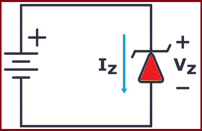
When a voltage (must be higher than the Zener voltage) is applied across the resistor and Zener diode, the diode starts conducting in reverse and keeps the voltage drop across it at a constant value of 3.3V.
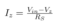
The rest of the voltage drops across the resistor. This means the resistor acts as a current-limiting resistor so that you can easily calculate the current by using Ohm’s law.

The resistor (RS) limits the maximum current that can flow through the circuit. If there is no load connected to the circuit all the current flows through the Zener diode, causing it to dissipate its maximum power.
A smaller value of resistor RS gives you a higher maximum current. But at the same time, you have to make sure that you don’t exceed the maximum power rating of the Zener. Therefore, it’s important to choose the right value of series resistance.
Example: Choosing a resistor for a 12V to 3.3V voltage regulator
In this example, you’re going to use a Zener diode that can handle up to 2W of power. What’s a suitable value for the resistor (RS)?

First, you need to find the maximum current that can flow through the Zener diode:

That means that the minimum value of the resistor is:

So a value of 14.5 Ω is the absolute minimum. But you can use higher resistances of course.
Next, you need to check how much current your load needs. The load resistor is 1 kΩ, so its current is calculated as follows:

That’s much lower than the 0.6A you’d get from the 14.5 Ω resistor, so no problem here.
If you want to use a higher resistor value, just use the following formula with your chosen resistor value and make sure that it’s above the current you need for your load:
For example, if you want to use a 100 Ω resistor, this would give you a maximum current of:

Still, high above the needed 0.0033A for the load, so you’re good to go.
That said, Zener diodes have their disadvantages. Check out this article about why Zener diodes make lousy voltage generators.
Wave-Shaping With the Zener
In the previous example, you saw how the Zener works with DC power. However, what happens when it’s used with AC power? How would it react to a constantly changing signal such as an audio signal?
Check out the following circuit:

In the above diagram, the Zener diode has a VZ of 5V, so if the waveform exceeds this limit, the diode will “clip off” the excess voltage from the input, resulting in a waveform with a flat top maintaining a constant output of 5V.
When forward-biased, the Zener diode behaves like a regular diode. So when the waveform reaches negative values below 0.7V, the Zener acts like a typical rectifier diode, resulting in output clipping at -0.7V.
Zener Diode Characteristics (The I-V Graph)

The I-V characteristics curve of a Zener diode is shown in the image above. By studying this graph, it becomes clear why Zener diodes are employed in reverse bias.
By observing the behavior of a Zener diode, you can notice that as the reverse voltage rises, the reverse current also increases gradually until it hits the Zener knee current, IZ (min). At this point, the breakdown effect starts, and the Zener impedance (ZZ), which is the internal resistance of the diode, begins to rapidly decrease as the reverse current increases.
In general, the breakdown voltage of the Zener (VZ) is fairly constant, although it increases slightly with increasing Zener current (IZ). VZ is commonly set at a value of the Zener current known as the IZ (min).
A Zener diode’s ability to maintain almost constant voltage in its breakdown region makes it suitable for regulating voltage even in the simplest voltage regulator applications.
A voltage regulator’s main role is to deliver a steady output voltage to a load connected in parallel. This is even when the supply voltage has ripples or the load current varies. Zener diodes can maintain a constant voltage output as long as their reverse breakdown region holding current does not drop below IZ (min).
Zener Diode Specifications
Some commonly used specifications for Zener diodes are as follows:
- Zener/Breakdown Voltage – The Zener or the reverse breakdown voltage ranges from 2.4 V to 200 V, sometimes it can go up to 1 kV while the maximum for the surface-mounted device is 47 V.
- Current Iz (max) – It is the maximum current at the rated Zener Voltage (Vz – 200μA to 200 A)
- Current Iz (min) – It is the minimum value of current required for the diode to break down.
- Power Rating – It denotes the maximum power the Zener diode can dissipate. It is given by the product of the voltage of the diode and the current flowing through it.
- Temperature Stability – Diodes around 5 V have the best stability
- Voltage Tolerance – It is typically ±5%
- Zener Resistance (Rz) – It is the resistance to the Zener diode exhibits.
Application of Zener Diode
Following are the applications of Zener diode:
Zener diode as a voltage regulator:
The zener diode is used as a Shunt voltage regulator for regulating voltage across small loads. The Zener diode is connected parallel to the load to make it reverse bias, and once the Zener diode exceeds knee voltage, the voltage across the load will become constant. The breakdown voltage of Zener diodes will be constant for a wide range of currents.
Zener diode in over-voltage protection:
When the input voltage is higher than the Zener breakage voltage, the voltage across the resistor drops resulting in a short circuit, this can be avoided by using the Zener diode.
Common Zener Diode Voltages
Here you have a table with the most common Zener voltages in diodes of 0.3 W and 1.3 W.
| 0.3W BZX55 zener diode | |||||||
| 2.4V | 2.7V | 3.0V | 3.3V | 3.6V | 3.9V | 4.3V | 4.7V |
| 5.1V | 5.6V | 6.2V | 6.8V | 7.5V | 8.2V | 9.1V | 10V |
| 11V | 12V | 13V | 15V | 16V | 18V | 20V | 22V |
| 24V | 27V | 30V | 33V | 36V | 39V | 43V | 47V |
| 1.3W BZX85 zener diode | |||||||
| .3V | 3.6V | 3.9V | 4.3V | 4.7V | 5.1V | 5.6 | 6.2V |
| 6.8V | 7.5V | 8.2V | 9.1V | 10V | 11V | 12V | 13V |
| 15V | 16V | 18V | 20V | 22V | 24V | 27V | 30V |
| 33V | 36V | 39V | 43V | 47V | 51V | 56V | 62V |

Leave a comment