
The Arduino Uno was officially released in October 2010 .since then it is one of the most popular microcontrollers in the world, especially among makers and hobbyists.
Since its initial release, the Arduino Uno has undergone a number of updates:
- Arduino Uno (Revision 1) – Released in October 2010. The initial version of the Arduino Uno featured a removable Atmel ATmega328 microcontroller and used the Atmel ATmega8U2 for USB connectivity. Note that Atmel is now Microchip.
- Arduino Uno (Revision 2) – This revision added four solder pads connecting two of the ATmega8U2’s pins. This allowed the ATmega8U2 to be replaced with a standalone circuit once the development phase was complete.
- Arduino Uno (Revision 3) – Released in November 2011. This was a major revision that changed the USB chip to an ATmega16U2 and added more pin headers for compatibility with future hardware. This revision is still available and has been “cloned” by many manufacturers. When people speak about “an Arduino,” this is the board they are talking about.
- Arduino Uno WiFi (Revision 2) – Released in 2018, this variant of the Uno added built-in WiFi connectivity through an ESP32 module. In addition to WiFi, it also offered enhanced features like a 6-axis IMU, temperature sensor, and crypto chip for secure communication. It was never very popular, but it is still available.There were also several “special edition” Arduino Unos produced, such as the Arduino Uno SMD Edition (which replaced the removable DIP ATmega328 chip with a surface-mount version)
There were also several “special edition” Arduino Unos produced, such as the Arduino Uno SMD Edition (which replaced the removable DIP ATmega328 chip with a surface-mount version)
Now, in mid-2023, we finally have a new revision of the Arduino Uno. Actually, we have two.
The Arduino Uno R4 Boards
Instead of just a single board, the new Arduino Uno R4 has been released as two.
- The Uno R4 WiFi – A board with Bluetooth and Wifi.
- The Uno R4 Minima – A less expensive, “stripped-down” version.
1.Arduino Uno R3
Arduino Uno is known as an open-source development board as it allows you to use this board to interact with real-world things by uploading programs on this board. There are many other microcontrollers like PIC microcontrollers, ST microcontrollers, Texas microcontrollers but Arduino is used mostly as it is inexpensive and can be used in various forms. It is based on ATMEL ATmega328p microcontroller.
It can interact with anything that is controlled by electricity in any way. It can also interact with motors, sensors, and electromagnets. In short, we can make devices that react and respond to the world by using this board. In short, we can say that Arduino is the brain of thousands of projects.

Different types of ARDUINO UNO Boards
Arduino makes a different type of development boards and each having different capabilities. Like Arduino Mega, Arduino UNO, Arduino Nano, Lily Pad Arduino, and much more because as advance our projects are, Arduino keeps on updating its development board to keep teachers, students and other interested people updated as these boards are being used in scientific research as well as many other advanced fields of robotics and many other fields. These boards are commonly used as they are inexpensive, cross-platform (IDE software which is used to make a code for these development boards can run on Linux, OSX and Windows operating system while some boards are limited only to windows), extensible and open-source hardware and software.
Introduction
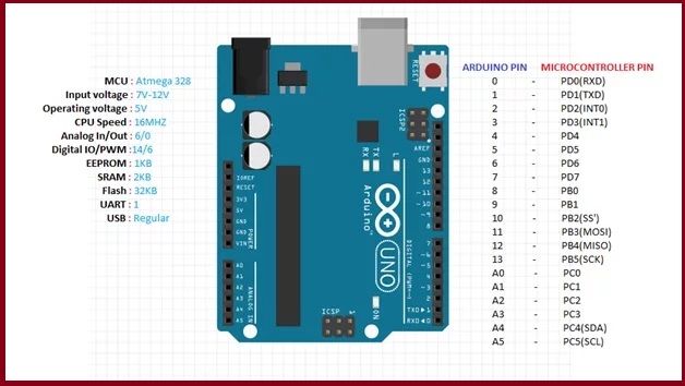
Arduino UNO is one of the famous microcontroller boards of the Arduino family and is developed by Arduino.cc. Basically Arduino.cc is an open-source platform and is mainly based upon AVR microcontroller Atmega328. It is one of the most economical boards of Arduino family and is widely used because of its small number of input-output pins and reduced size as compared to Arduino mega which is the big brother of Arduino UNO. In this article, we are going to briefly discuss Arduino UNO. We will discuss its specifications, pin configuration, dimensions,applications and projects in which this board is used.
Arduino Uno R3 Pinout Diagram
Pinout diagram shows that each pin has multiple functions such as PWM, interrupts, general-purpose input-output and analog channel. But we can use only one function of each pin at a time.It consists of a total of 14 GPIO pins. Not all pins have a PWM feature.

Pin Configuration Description and their use
In this section, we will see the function of each pin. How can we initialize these pins for a specific feature?
GPIO pins
As mentioned in the last section, Arduino Uno has fourteen digital I/O pins. We can use all these pins either as digital input pins or digital output pins. These pins have only 2 states i.e. high or low or in simple words either 5 V or 0 V no in-between values. These pins are mostly used to sense the digital voltage level presence when the switch is open or closed). For example, when the switch connected with Arduino Uno digital input is open, it will sense zero voltage level. If the switch is closed, it will sense 5 volts.
- To initialize any pin as an input or output, we use pinMode(pin_number, mode) function. For example, using this function like this ‘pinMode(13, OUTPUT)’ will initialize the pin number 13 as a digital output pin.
- Similarly this ‘pinMode(13, INPUT)’ will initialize the pin as a digital input pin.
- digitalWrite(pin_number, state) function makes the digital output pin active high or low depending state parameter. This parameter can be either HIGH or LOW.
- digitalRead() function read the state of a digital input pin and returns either logic high or low according to the voltage level on the input pin.
Analog Channel Pins
Arduino Uno offers six analog channels. The header on the left side of the board has all these analog pins together. This diagram shows the Pinout location of the analog pins.
Starting from A0 to A5 and they come up with a resolution of 10 bits. They provide the flexibility of connecting any external analog device with these pins. These pins can read analog voltage from 0 V to 5 V. But they can be configured to lower range by using the AREF pin or analogReference () function available in Arduino IDE. But the maximum voltage we can read directly with these analog channels is 5 volts. However, we can use step down voltage circuits to measure higher voltage.
ADC (analog to digital converter) is used to sample these pins. These pins take an analog signal and by using ADC convertor they convert this analog signal to digital number between 0 – 1023.

Analog channel Examples:
To use analog channels, we use this function
int analogoutput = analogRead(int pin_number);
analogRead() function reads the analog voltage from a pin number specified as an argument to this function. We save the output value in an integer type variable.
Arduino PWM Pins
Development Board has 14 GPIO pin. But, only six of them have a pulse width modulation feature. Pin number, 5, 6, 9, 10, and 11 provide PWM output. All of them have an 8-bit resolution.

It is just like an analog output function. PWM controls LEDs, motors and other actuators. The analogWrite(pin_number, duty_cycle) function provides PWM output with a specified duty cycle. The duty cycle can vary between 0-100% or 0-255. For example, analogWrite(5, 127) function generates a PWM on pin number 5 with a duty cycle of 50%.
Other Pins
- USB port
- TX and RX pins (for serial communication)
- SPI (serial peripheral interface)
- External adaptor to deliver power to this board by external power supply up to 12 volts (board will make use of its voltage regulator and will make this voltage up to 5 V or 3.3 V as per our requirements)
- Reset Pin: Used to reset our whole board and takes it to the initial stage of the running program. For instance our board gets hang in the middle of our running program then we can make use of this pin and this pin will clear everything up and starts program from beginning
- ICSP connector (Used to bypass USB port and interfacing our board directly as serial device. This port is essential to reboot load our chip if it gets corrupted and we are not able to talk to our computer)
MEMORY of ARDUINO UNO R3
- Flash Memory: 13KB (used to store a number of instructions in code form)
- SRAM of 2 KB
- 1 KB EPROM
KEY FEATURES of ARDUINO UNO R3
- 16 MHz crystal oscillator
- Operating voltage is 5 V and it can be achieved by using a USB port or by using an external adaptor.
- An external micro SD card is supported
- This board comes with a built-in feature of voltage regulation i.e. when the device is connected to other external devices it keeps voltage under control thus preventing the board from damage.
- Easy USB interface i.e. simply plug your external device with this port and your device is ready to use. This interface is also used to register your board as a virtual serial port on your computer and the advantage is that this type of serial communication setup is extremely easy and convenient.
- 16 MHz clock makes it fast enough for most of the applications.
- Onboard LED for easy and fast debugging of our code
- Micro SD cards can be used if the functionality or nature of our project goes complex to make our board store more information.
ARDUINO UNO R3 PROGRAMMING
- Like other development boards of Arduino family, also uses Arduino IDE software to make sketches (Arduino programs are called sketches)
- Sketches that are developed on Arduino IDE can be transferred directly by connecting our computer via USB port.
- IDE is compatible with Linux, MAC or Windows operating system
- Programming languages C and C++ are used
- Thousands of preloaded sketches are easily available which we can use in order to get Arduino to do something according to our requirements.
CODING of ARDUINO UNO R3
Important things to remember when you are going to write code:
- The sketch is an Arduino program
- All code in Arduino sketch is going to process from top to bottom
- These sketches are usually broken in 10 parts:
- It starts with a header that explains what we are going to do in our sketch
- Global variables are defined
- Constant names are assigned to different Arduino pins
- Initial variables are set and configured
- After initial variables setting, it begins with a setup routine in which we set initial conditions of variables if needed
- Run preliminary code that we want to run only once and at this point serial communication is initiated for running serial monitor
- From the setup function, we jump to loop routine and keep in mind that it is the main routine of sketch
- The loop routine will be executed over and over as long as our sketch continues to run.
- After loop routine, many user-defined functions are listed and these functions work only when they are called in setup or loop function
- Execution of these user-defined functions depends on whether they are called in setup function or loop function. Whenever a user-defined function is called it goes to that function execute it and then comes back to the exact next line of sketch from which that function was called.
- Only 2 parts of the sketch are mandatory i.e. loop and setup function
SHIELDS COMPATIBILITY of ARDUINO UNO
In order to make our Arduino UNO perform a special function, we will use shields (an expensive adaptor plugged over top of the board). A countless number of Arduino shields are available. The selection of shields depends on the requirement and functionality of our project. Before buying any shield, make sure that the operating voltage of that shield doesn’t exceed the voltage of our board otherwise it will destroy our board. So after making sure of its operating voltage we can use any one of the shields available in the market. Some of the important shields which are widely used are listed below:
- Ethernet Shield
- Wireless Shield
- Motor Shield
APPLICATIONS of ARDUINO UNO
As discussed earlier, the most economical and inexpensive board is Arduino UNO. So a wide number of applications are supported by this board. Some important applications that are developed using Arduino UNO are listed below
- Embedded system
- Robotics
- Motion control rig
- DC motor control ( using H-bridge )
- Ardupilot ( drone hardware and software )
- Defense and security defense
- Parking lot counter
- Home and industrial automation
- Game Duino ( for creating retro 2D games )
- Water quality testing
- Data loggers ( used in scientific research )
- Xoscillo ( open-source oscilloscope )
- Count down timer for traffic lights
2.The Arduino UNO R4 Minima
Description
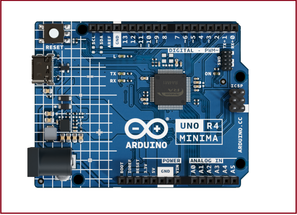
The Arduino UNO R4 Minima (from here on referred to as UNO R4 Minima) is the first UNO board to feature a 32-bit microcontroller. It features a RA4M1 series microcontroller from Renesas (R7FA4M1AB3CFM#AA0), which embeds a 48 MHz Arm® Cortex®-M4 microprocessor. The UNO R4’s memory is larger than its predecessors, with 256 kB flash, 32 kB SRAM and 8 kB data memory (EEPROM).
The UNO R4 Minima board’s operating voltage is 5 V, making it hardware compatible with UNO form factor accessories with the same operating voltage. Shields designed for previous UNO revisions are therefore safe to use with this board but are not guaranteed to be software compatible due to the change of microcontroller.
Features
![]() R7FA4M1AB3CFM#AA0
R7FA4M1AB3CFM#AA0
48 MHz Arm® Cortex®-M4 microprocessor with a floating point unit (FPU) 5 V operating voltage
Real-time Clock (RTC) Memory Protection Unit (MPU) Digital Analog Converter (DAC)
![]() Memory
Memory
256 kB Flash Memory 32 kB SRAM
8 kB Data Memory (EEPROM)
![]() Pins
Pins
14x digital pins (GPIO), D0-D13 6x analog input pins (ADC), A0-A5
6x PWM pins: D3,D5,D6,D9,D10,D11
![]() Peripherals
Peripherals
Capacitive Touch Sensing Unit (CTSU) USB 2.0 Full-Speed Module (USBFS) up to 14-bit ADC
up to 12-bit DAC
Operational Amplifier (OPAMP)
![]() Power
Power
Recommended input voltage (VIN) is 6-24 V 5 V operating voltage
Barrel jack connected to VIN pin Power via USB-C® at 5 V
Schottky diodes for overvoltage and reverse polarity protection
![]() Communication
Communication
1x UART (pin D0, D1)
1x SPI (pin D10-D13, ICSP header) 1x I²C (pin A4, A5, SDA, SCL)
1x CAN (pin D4, D5, external transceiver is required)
1 : The Board
Application Examples
The UNO R4 Minima is the first UNO series 32-bit development board, being previously based on 8-bit AVR microcontrollers. There are thousands of guides, tutorials and books written about the UNO board, where UNO R4 Minima continues its legacy.
The board features the standard 14 digital I/O ports, 6 analog channels, dedicated pins for I²C, SPI and UART connections. Compared to its predecessors the board has a much larger memory: 8 times more flash memory (256 kB) and 16 times more SRAM (32 kB).
Entry level projects: If this is your first project within coding and electronics, the UNO R4 Minima is a good fit. It is easy to get started with and has a lot of online documentation (both official + 3rd party).
Easy power management: the UNO R4 has barrel jack connector and supports input voltages from 6-24 V. This connector is widely popular and removes the need for additional circuitry required to stepping down the voltage.
Cross compatibility: the UNO form factor automatically makes it compatible with hundreds of existing third-party shields and other accessories.
Related Products
UNO R3
UNO R3 SMD UNO R4 WiFi
Rating
2 : Recommended Operating Conditions
| Symbol | Description | Min | Typ | Max | Unit |
| VIN | Input voltage from VIN pad / DC Jack | 6 | 7.0 | 24 | V |
| VUSB | Input voltage from USB connector | 4.8 | 5.0 | 5.5 | V |
| TOP | Operating Temperature | -40 | 25 | 85 | °C |
Functional Overview

Arduino R4 Minima Block Diagram
4 : Board Topology
Front View

Top View of Arduino UNO R4 Minima
| Ref. | Description | Ref. | Description |
| U1 | R7FA4M1AB3CFM#AA0 Microcontroller IC | J4 | DC Jack |
| U2 | ISL854102FRZ-T Buck Converter | DL1 | LED TX (serial transmit) |
| PB1 | RESET Button | DL2 | LED RX (serial receive) |
| JANALOG | Analog input/output headers | DL3 | LED Power |
| JDIGITAL | Digital input/output headers | DL4 | LED SCK (serial clock) |
| J1 | ICSP header (SPI) | D2 | PMEG6020AELRX Schottky Diode |
| J2 | SWD/JTAG Connector | D3 | PMEG6020AELRX Schottky Diode |
| J3 | CX90B-16P USB-C® connector | D4 | PRTR5V0U2X,215 ESD Protection |
Back View

Back View of Arduino R4 Minima
5 : Microcontroller (R7FA4M1AB3CFM#AA0)
The UNO R4 Minima is based on the 32-bit RA4M1 series microcontroller, R7FA4M1AB3CFM#AA0, from Renesas, which uses a 48 MHz Arm® Cortex®-M4 microprocessor with a floating point unit (FPU).
On the UNO R4 Minima, the operating voltage is fixed at 5 V to be fully retro compatible with shields, accessories & circuits originally designed for older UNO revisions.
The R7FA4M1AB3CFM#AA0 features:
256 kB flash / 32 kB SRAM / 8 kB data flash (EEPROM) Real-time Clock (RTC)
4x Direct Memory Access Controller (DMAC) up to 14-bit ADC
up to 12-bit DAC OPAMP
1x CAN bus
6 : USB Connector
The UNO R4 Minima has one USB-C® port, used to power and program your board as well as sending & receiving serial communication.
Note: You should not power the board with more than 5 V via the USB-C® port.
7 : Digital Analog Converter (DAC)
The UNO R4 Minima has a DAC with up to 12-bit resolution attached to the A0 analog pin. A DAC is used to convert a digital signal to an analog signal.
8 : Power Options
Power can either be supplied via the VIN pin, the barrel jack, or via USB-C® connector. If power is supplied via VIN, the ISL854102FRZ buck converter steps the voltage down to 5 V.
The VUSB, barrel jack connector and VIN pins are connected to the ISL854102FRZ buck converter, with Schottky diodes in place for reverse polarity & overvoltage protection respectively.
Power via USB supplies about ~4.7 V (due to Schottky drop) to the RA4M1 microcontroller.
Power Tree

Arduino UNO R4 Minima power tree.
Pin Voltage
The UNO R4 Minima operates on 5 V, as does all pins on this board except for the 3.3V pin. This pin draws power from the VCC_USB pin on the R7FA4M1AB3CFM#AA0, and is not connected to the buck converter.
Pin Current
The GPIOs on the R7FA4M1AB3CFM#AA0 microcontroller can handle up to 8 mA. Never connect devices that draw higher current directly to a GPIO.
In case you need to power external devices that require more power, e.g. servo motors, use an external power supply.
Mechanical Information
9 : Pinout

Pinout for UNO R4 Minima.
Analog
| Pin | Function | Type | Description |
| 1 | BOOT | MD | Mode selection |
| 2 | IOREF | IOREF | Reference for digital logic V – connected to 5V |
| 3 | Reset | Reset | Reset |
| 4 | +3V3 | Power | +3V3 Power Rail |
| 5 | +5V | Power | +5V Power Rail |
| 6 | GND | Power | Ground |
| 7 | GND | Power | Ground |
| 8 | VIN | Power | Voltage Input |
| 9 | A0 | Analog | Analog input 0 / DAC |
| 10 | A1 | Analog | Analog input 1 / OPAMP+ |
| 11 | A2 | Analog | Analog input 2 / OPAMP- |
| 12 | A3 | Analog | Analog input 3 / OPAMPOut |
| 13 | A4 | Analog | Analog input 4 / I²C Serial Datal (SDA) |
| 14 | A5 | Analog | Analog input 5 / I²C Serial Clock (SCL) |
Digital
| Pin | Function | Type | Description |
| 1 | SCL | Digital | I²C Serial Clock (SCL) |
| 2 | SDA | Digital | I²C Serial Datal (SDA) |
| 3 | AREF | Digital | Analog Reference Voltage |
| 4 | GND | Power | Ground |
| 5 | D13/SCK | Digital | GPIO 13 / SPI Clock |
| 6 | D12/CIPO | Digital | GPIO 12 / SPI Controller In Peripheral Out |
| 7 | D11/COPI | Digital | GPIO 11 (PWM) / SPI Controller Out Peripheral In |
| 8 | D10/CS | Digital | GPIO 10 (PWM) / SPI Chip Select |
| 9 | D9 | Digital | GPIO 9 (PWM~) |
| 10 | D8 | Digital | GPIO 8 |
| 11 | D7 | Digital | GPIO 7 |
| 12 | D6 | Digital | GPIO 6 (PWM~) |
| 13 | D5/CANRX0 | Digital | GPIO 5 (PWM~) / CAN Transmitter (TX) |
| 14 | D4/CANTX0 | Digital | GPIO 4 / CAN Receiver (RX) |
| 15 | D3 | Digital | GPIO 3 (PWM~) |
| 16 | D2 | Digital | GPIO 2 |
| 17 | D1/TX0 | Digital | GPIO 1 / Serial 0 Transmitter (TX) |
| 18 | D0/TX0 | Digital | GPIO 0 / Serial 0 Receiver (RX) |
ICSP
| Pin | Function | Type | Description |
| 1 | CIPO | Internal | Controller In Peripheral Out |
| 2 | +5V | Internal | Power Supply of 5 V |
| 3 | SCK | Internal | Serial Clock |
| 4 | COPI | Internal | Controller Out Peripheral In |
| 5 | RESET | Internal | Reset |
| 6 | GND | Internal | Ground |
SWD/JTAG
| Pin | Function | Type | Description |
| 1 | +5V | Internal | Power Supply of 5V |
| 2 | SWDIO | Internal | Data I/O pin |
| 3 | GND | Internal | Ground |
| 4 | SWCLK | Internal | Clock Pin |
| 5 | GND | Internal | Ground |
| 6 | NC | Internal | Not connected |
| 7 | RX | Internal | Serial Receiver |
| 8 | TX | Internal | Serial Transmitter |
| 9 | GND | Internal | Ground |
| 10 | NC | Internal | Not connected |
3.The Arduino UNO R4 WiFi

Description
The Arduino® UNO R4 WiFi is the first UNO board to feature a 32-bit microcontroller and an ESP32-S3 Wi-Fi® module (ESP32-S3-MINI-1-N8). It features a RA4M1 series microcontroller from Renesas (R7FA4M1AB3CFM#AA0), based on a 48 MHz Arm® Cortex®-M4 microprocessor. The UNO R4 WiFi’s memory is larger than its predecessors, with 256 kB flash, 32 kB SRAM and 8 kB of EEPROM.
The RA4M1’s operating voltage is fixed at 5 V, whereas the ESP32-S3 module is 3.3 V. Communication between these two MCUs are performed via a logic level translator (TXB0108DQSR).
Features
The R7FA4M1AB3CFM#AA0,often referred to as RA4M1 in this datasheet,is the main MCU on the UNOR4WiFi, connected to all pin headers on the board as well as all communication buses.
![]() Overview
Overview
48 MHzArm®Cortex®-M4 microprocessor with a floating point unit(FPU) 5 V operating voltage
Real-time Clock (RTC) MemoryProtectionUnit(MPU)
Digital-to-analog Converter (DAC)
![]() Memory
Memory
256kB FlashMemory 32 kB SRAM
8 kB Data Memory (EEPROM)
![]() Peripherals
Peripherals
CapacitiveTouch Sensing Unit(CTSU)
USB 2.0 Full-Speed Module (USBFS)
14-bit ADC
Up to 12-bit DAC
Operational Amplifier (OPAMP)
![]() Power
Power
Operating voltage for RA4M1 is 5 V
Recommended input voltage (VIN)is6-24V
Barrel jack connected to VIN pin (6-24 V)
Power via USB-C® at 5 V
![]() Communication
Communication
1xUART(pinD0,D1)
1xSPI(pinD10-D13,ICSPheader)
1x I2C (pin A4, A5, SDA, SCL)
1x CAN (pin D4, D5, external transceiver is required)
TheESP32-S3-MINI-1-N8isthesecondaryMCUwithabuilt-inantennaforWi-Fi®&Bluetooth®connectivity.This module operates on 3.3 V and communicates with the RA4M1 using a logic level translator (TXB0108DQSR).
![]() Overview
Overview
Xtensa® dual-core 32-bit LX7 microprocessor
3.3 V operating voltage
40 MHz crystal oscillator
![]() Wi-Fi®
Wi-Fi®
Wi-Fi®support with 802.11b/g/n standard(Wi-Fi®4)
Bit rate at up to 150 Mbps
2.4 GHz band
![]() Bluetooth®
Bluetooth®
Bluetooth® 5
ESP32-S3-MINI-1-N8 datasheet
1 : TheBoard
ApplicationExamples
The UNO R4 WiFi is part of the first UNO series of 32-bit development boards, being previously based on 8-bit AVR microcontrollers. There are thousands of guides, tutorials and books written about the UNO board, where the UNO R4 WiFi continues its legacy.The board features 14 digital I/O ports, 6 analog channels, dedicated pins for I2C, SPI and UART connections. It has asignificantly larger memory: 8 times more flash memory (256 kB) and 16 times more SRAM (32 kB). With a 48 MHz clock speed, it is also 3x faster than its predecessors. In addition, it features an ESP32-S3 module for Wi-Fi® & Bluetooth® connectivity, as well as a built-in 12×8 LED matrix,making one of the most visually unique Arduino board to date. The LED matrix is fully programmable, where you can load anything from still frames to custom animations. Entry-level projects: If this is your first project within coding and electronics, the UNO R4 WiFi is a good fit. It is easy to get started with, and it has a lot of online documentation. Easy IoT applications: build projects without writing any networking code in the Arduino IoT Cloud. Monitor your board,connect it with other boards and services, and develop cool IoT projects.LED Matrix: the 12×8 LED matrix on the board can be used for showing animations, text scrolling, create mini-games and much more, being the perfect feature to give your project more personality.
Related Products
UNO R3
UNO R3 SMD
UNO R4 Minima
Rating
2 : RecommendedOperatingConditions
| Symbol | Description | Min | Typ | Max | Unit |
| VIN | Input voltage from VIN pad / DC Jack | 6 | 7.0 | 24 | V |
| VUSB | Input voltage from USB connector | 4.8 | 5.0 | 5.5 | V |
| TOP | Operating Temperature | -40 | 25 | 85 | °C |
Note:VD Dcontrols the logic level and is connected tothe 5V power rail. VAREF is for the analog logic.
Functional Overview
3 : BlockDiagram

Arduino R4 WiFi Block Diagram
4 : BoardTopology
FrontView

Top View of Arduino UNO R4 WiFi
| Ref. | Description |
| U1 | R7FA4M1AB3CFM#AA0Microcontroller IC |
| U2 | NLASB3157DFT2G Multiplexer |
| U3 | ISL854102FRZ-T Buck Converter |
| U4 | TXB0108DQSR logic level translator (5 V – 3.3 V) |
| U5 | SGM2205-3.3XKC3G/TR 3.3 V linear regulator |
| U6 | NLASB3157DFT2G Multiplexer |
| U_LEDMATRIX | 12×8 LED Red Matrix |
| M1 | ESP32-S3-MINI-1-N8 |
| PB1 | RESET Button |
| JANALOG | Analog input/output headers |
| JDIGITAL | Digital input/output headers |
| JOFF | OFF,VRTCheader |
| J1 | CX90B-16P USB-C® connector |
| J2 | SM04B-SRSS-TB(LF)(SN) I2C connector |
| J3 | ICSP header (SPI) |
| J5 | DC Jack |
| J6 | ESP header |
| DL1 | LED TX (serial transmit) |
| DL2 | LED RX (serial receive) |
| DL3 | LED Power (green) |
| DL4 | LED SCK (serial clock) |
| Ref. | Description |
| D1 | PMEG6020AELRX Schottky Diode |
| D2 | PMEG6020AELRX Schottky Diode |
| D3 | PRTR5V0U2X,215ESD Protection |
5 : Microcontroller(R7FA4M1AB3CFM#AA0)
The UNO R4 WiFi is based on the32-bit RA4M1 series microcontroller, R7FA4M1AB3CFM#AA0, from Renesas,which uses a 48 MHz Arm® Cortex®-M4 microprocessor with a floating point unit (FPU).TheoperatingvoltagefortheRA4M1isfixedat5Vastobehardwarecompatiblewithshields,accessories&circuits based on previous Arduino UNO boards.
TheR7FA4M1AB3CFM#AA0features:
256 kB flash / 32 kB SRAM / 8 kB data flash (EEPROM)
Real-time Clock (RTC)
4xDirectMemoryAccessController(DMAC)
14-bit ADC
Upto12-bitDAC
OPAMP
CAN bus
6 : Wi-Fi®/Bluetooth®Module(ESP32-S3-MINI-1-N8)
TheWi-Fi®/Bluetooth®LE module on the UNO R4 WiFi is from the ESP32-S3SoCs .It features the Xtensa® dual-core 32-bit LX7 MCU, a built-in antenna and support for 2.4 GHz bands.
The ESP32-S3-MINI-1-N8 features:
Wi-Fi®4-2.4GHzband
Bluetooth® 5 LE support
3.3Voperatingvoltage
384 kB ROM
512kB SRAM
Up to 150 Mbps bit rate
This module acts as a secondary MCU on the UNO R4 WiFi,and communicates with the RA4M1 MCU using alogic level translator. Note that this module operates on 3.3 V as opposed to the RA4M1’s 5 V operating voltage.
ESP Header

ESPheader.
The header located close to the RESET button can be used to access the ESP32-S3 module directly. The pins accessible are:
ESP_IO42– MTMS debugging (Pin 1)
ESP_IO41– MTDI debugging (Pin 2)
ESP_TXD0-Serial Transmit(UART)(Pin3)
ESP_DOWNLOAD– boot (Pin 4)
ESP_RXD0-Serial Receive(UART)(Pin 5)
GND– ground (Pin 6)
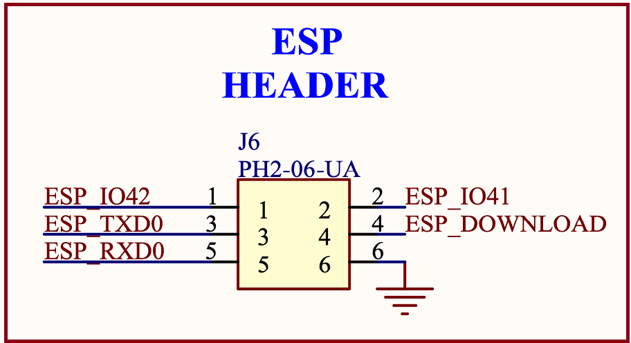
ESPheader(schematic)
USB Bridge
When programming the UNO R4 WiFi,the RA4M1 MCU is programmed via the ESP32-S3 module by default.TheU2 and U6 switches can switch the USB communication to go directly to the RA4M1 MCU, by writing a high state to the P408pin (D40).

SolderingtogethertheSJ1padspermanentlysetstheUSBcommunicationdirectlytotheRA4M1,bypassingtheESP32- S3.
7 : USBConnector
TheUNOR4WiFihasoneUSB-C®port,usedtopowerandprogramyourboardaswellassending&receivingserial communication.
Note:The board should not be powered with more than 5 V via the USB-C® port.
8 : LEDMatrix
TheUNOR4WiFifeaturesa12x8matrixofredLEDs(U_LEDMATRIX),connectedusingthetechniqueknownas charlieplexing.
The following pins on the RA4M1 MCU are used for the matrix:
P003 P004 P011 P012 P013 P015 P204 P205 P206 P212 P213

LEDmatrixschematics.
TheseLEDscanbeaccessedasanarray,usingaspecificlibrary.Seethemappingbelow:
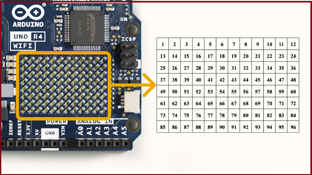
LEDmatrixnumbermapping.
Thismatrixcanbeusedforanumberofprojectsandprototypingpurposes,andsupportsanimation,simplegame designs and scrolling text among other things.
9 : DigitalAnalogConverter(DAC)
TheUNOR4WiFihasaDACwithupto12-bitresolutionattachedtotheA0analogpin.ADACisusedtoconverta digital signal to an analog signal.
The DAC can be used for signal generation for e.g. audio applications, like generating and altering sawtooth wave.
10 : I2CConnector
TheI2CconnectorSM04B-SRSS-TB(LF)(SN)isconnectedtoasecondaryI2Cbusontheboard.Notethatthis connector is powered via 3.3 V.
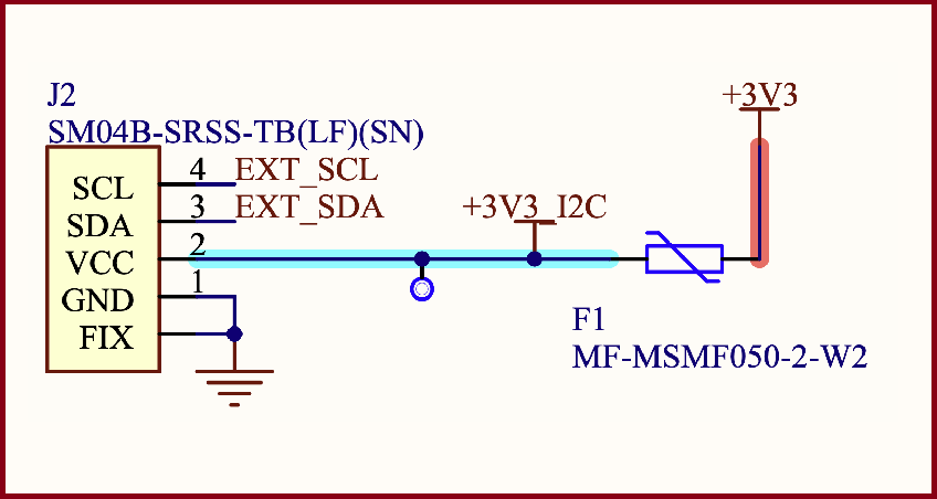
I2Cconnector.
This connector also shares the following pin connections:
JANALOG header
A4 A5
JDIGITALheader
SDA SCL
Note:asA4/A5isconnectedtothemainI2Cbus,theseshouldnotbeusedasADCinputswheneverthebusisinuse. You can however connect I2C devices to each of these pins and connectors simultaneously.
11 : PowerOptions
PowercaneitherbesuppliedviatheVINpin,orviaUSB-C®connector.IfpowerissuppliedviaVIN,theISL854102FRZ buck converter steps the voltage down to 5 V.
BothVUSBandVINpinsareconnectedtotheISL854102FRZbuckconverter,withSchottkydiodesinplaceforreverse polarity & overvoltage protection respectively.
Power via USB supplies about ~4.7 V (due to Schottky drop) to the RA4M1 MCU.
Thelinearregulator(SGM2205-3.3XKC3G/TR)converts5VfromeitherthebuckconverterorUSB,andprovides3.3V to a number of components, including the ESP32-S3 module.
PowerTree

ArduinoUNOR4WiFipowertree.
PinVoltage
ThegeneraloperatingvoltageforUNOR4WiFiis5 V,howevertheESP32-S3module’soperatingvoltageis3.3 V.
Note:ItisveryimportantthatESP32-S3’spins(3.3V)donotcomeincontactwithanyoftheRA4M1’spins(5V),asthis may damage the circuits.
Pin Current
TheGPIOsontheR7FA4M1AB3CFM#AA0microcontrollercansafelyhandleupto8mAofcurrent.Neverconnect devices that draw higher current directly to a GPIO as this may damage the circuit.
Forpowering e.g. servo motors, always use an external power supply.
Mechanical Information
12 : Pinout
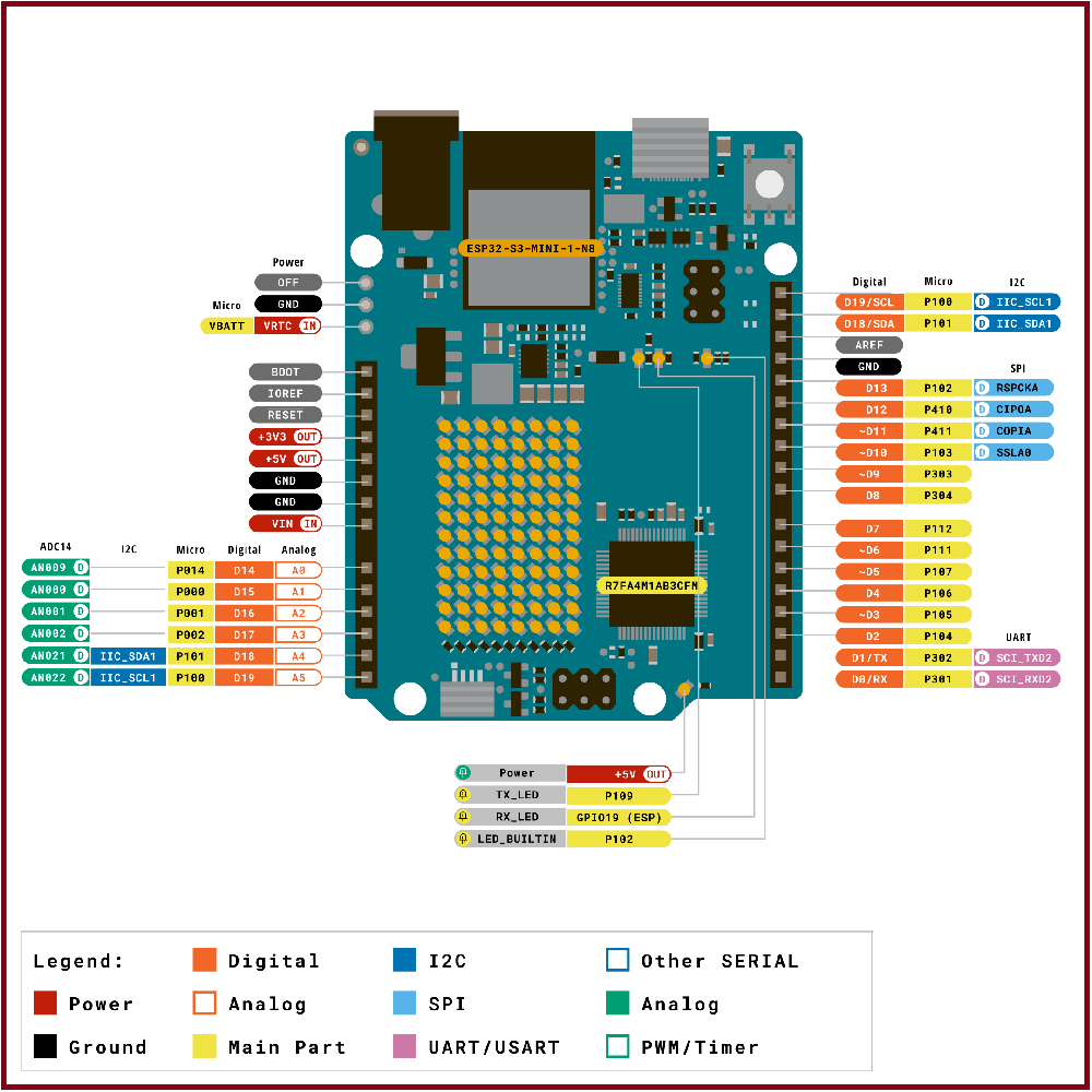
PinoutforUNOR4WiFi.
Analog
| Pin | Function | Type | Description |
| 1 | BOOT | NC | Not Connected |
| 2 | IOREF | IOREF | Reference for digital logic V – connected to 5 V |
| 3 | Reset | Reset | Reset |
| 4 | +3V3 | Power | +3V3 Power Rail |
| 5 | +5V | Power | +5V Power Rail |
| 6 | GND | Power | Ground |
| 7 | GND | Power | Ground |
| 8 | VIN | Power | VoltageInput |
| 9 | A0 | Analog | Analog input 0 / DAC |
| 10 | A1 | Analog | Analog input 1 / OPAMP+ |
| 11 | A2 | Analog | Analog input 2 / OPAMP- |
| 12 | A3 | Analog | Analog input 3 / OPAMPOut |
| 13 | A4 | Analog | Analog input 4 / I2C Serial Datal (SDA) |
| 14 | A5 | Analog | Analog input 5 / I2C Serial Clock (SCL) |
Digital
| Pin | Function | Type | Description |
| 1 | SCL | Digital | I2C Serial Clock (SCL) |
| 2 | SDA | Digital | I2C Serial Datal (SDA) |
| 3 | AREF | Digital | Analog Reference Voltage |
| 4 | GND | Power | Ground |
| 5 | D13/SCK/CANRX0 | Digital | GPIO 13 / SPI Clock / CAN Receiver (RX) |
| 6 | D12/CIPO | Digital | GPIO 12 / SPI Controller In Peripheral Out |
| 7 | D11/COPI | Digital | GPIO11(PWM)/SPIControllerOutPeripheralIn |
| 8 | D10/CS/CANTX0 | Digital | GPIO10(PWM)/ SPIChipSelect /CANTransmitter (TX) |
| 9 | D9 | Digital | GPIO 9 (PWM~) |
| 10 | D8 | Digital | GPIO 8 |
| 11 | D7 | Digital | GPIO 7 |
| 12 | D6 | Digital | GPIO 6 (PWM~) |
| 13 | D5 | Digital | GPIO 5 (PWM~) |
| 14 | D4 | Digital | GPIO 4 |
| 15 | D3 | Digital | GPIO 3 (PWM~) |
| 16 | D2 | Digital | GPIO 2 |
| 17 | D1/TX0 | Digital | GPIO1/Serial0Transmitter(TX) |
| 18 | D0/TX0 | Digital | GPIO 0 / Serial 0 Receiver(RX) |
OFF
| Pin | Function | Type | Description |
| 1 | OFF | Power | For controlling power supply |
| 2 | GND | Power | Ground |
| 1 | VRTC | Power | BatteryconnectiontopowerRTC only |
ICSP
| Pin | Function | Type | Description |
| 1 | CIPO | Internal | Controller In Peripheral Out |
| 2 | +5V | Internal | Power Supply of 5 V |
| 3 | SCK | Internal | Serial Clock |
| 4 | COPI | Internal | Controller Out Peripheral In |
| 5 | RESET | Internal | Reset |
| 6 | GND | Internal | Ground |
Difference :
The main difference is the 32-bit 48 MHz Arm Cortex-M4 microcontroller in R4 compared to the 8-bit 16 MHz ATmega328p microcontroller in R3. R4 also has a USB-C connector, RTC, real DAC channel, and support for CAN protocol. The WiFi version of R4 has an additional onboard 12×8 LED matrix and one Qwiic connector.
| Difference | UNO R3 | UNO R4 Wifi |
| Microcontroller | 8-bit ATmega328p | 32-bit Renesas RA4M1 |
| Clock frequency | 16 MHz | 48 MHz |
| Wireless module | NO | ESP32-S3 Mini |
| Memory | 2KB SRAM, 32KB FLASH, 1KB EEPROM | 256 kB Flash, 32 kB RAM ESP: 384 kB ROM, 512 kB SRAM |
| RTC | NO | YES |
| Input voltage (VIN) | 6-20 V | 6-24 V |
| Digital I/O pins | 14 | |
| Analog input pins | 6(10-bit) | 6(14-bit) |
| PWM pins | 6(12-bit) | 6(12-bit) |
| DAC pin | NO | 1(12-bit) |
| CAN Bus | NO | 1 |
| Dimensions | 68.58 x 53.44 mm | 68.6 x 53.4 mm |
| Weight | 25g | ——– |
| Price | 1200/- rupees | 2000/-rupees |

Leave a comment