
C Build Process is considered one of the most important topics in the field of Embedded Software and it’s the most famous question you will be asked in any Embedded Software interview.
Today we will talk about each step of this process in details to help you get a better understanding of this process.

C Build Process is the process of converting the high level source code representation of your embedded software into an executable binary image. This Process involves many steps and tools but the main three distinct steps of this process are:
- Each of the source files must be compiled or assembled into an object file.
- All of the object files that result from the first step must be linked together to produce a single object file, called the relocatable program.
- Physical memory addresses must be assigned to the relative offsets within the relocatable program in a process called relocation.
The result of the final step is a file containing an executable binary image that is ready to run on the embedded system.
So, let’s begin to discuss every step of this process in more details to be able to understand it better.
1.Pre-processor:
Pre-processing is the first stage of C Build process in which all the pre-processor directives are evaluated.
- The input file for this stage is *.c file.

- The output file is *.i or pre-processed file.
- The pre-processor strips out comments from the input c file. Evaluate pre-processor directive by making substitution for lines started with #, and then produces a pure C code without any pre-processor directives.
- Note that if a bug/error happened in the pre-processor stage you normally won’t know its place as the output of the pre-processor goes directly into compiler, the error will be likely at the lines you used the pre-processor directive.
2.compiler:

In this stage the C code gets converted into architecture specific assembly by the compiler; this conversion is not a one to one mapping of lines but instead a decomposition of C operations into numerous assembly operations. Each operation itself is a very basic task.
- The input file for this stage is *.i file.
- The output file is *.s or *.asm file.
To understand what exactly happens in this stage, we have to know how the compiler works and what is its components.

The first part of the compiler is called Front End: in which, the analysis of program syntax and semantics happens.

- First stage of the front-end part of the compiler is scanning the input text and Tokenization by identifying tokens such as keywords, identifiers, operators, and literals, then passing the scanned token to the parsing tool that ensures tokens are organized according to C rules to avoid compiler syntax errors.
- Second stage of the front-end of the compiler is checking if the sentence that has been parsed has the right meaning. And, this semantic check, if it fails you get a Semantic Error.
- One of the key things that really happens in the semantic analysis is to do with all variables that are present in the program. And for that matter, the compiler maintains the information of all the declared variables in a structure called symbol table. Once the variable is locked up, it gets its attributes; the attributes are its type, scope, and so on.
- When the statement is found to be semantically meaningful and is correct, the compiler undertakes its next action, which is to translate this sentence that is being seen into an internal representation called as the intermediate representation; the idea here is to take the high level language construct, regardless of the language, and to convert it into form which is closer to the assembly; to be able to compile different languages on different targets.
Types of semantic errors:
- Undeclared variable that is being used without declaration.
- Unavailable variables in a given scope, although they are declared.
- Incompatible types, for example, if you looked up a variable name and that variable name happens to be a character, then the usage of this particular name should not be part of addition statement, for example. Because it’s meaningless to add a character to something else.
The second part of the compiler is called Back End: in which, the optimization and code generation happens.
- First stage of the back-end part of the compiler is optimization; nowadays, compilers are smart enough to able to not just compile the code, but also to provide some optimization.
Optimisation:
- Optimisation transforms the code into a functionally-equivalent, but smaller or faster form. Optimisation is usually a multi-level process. Common optimisations include inline expansion of functions, dead code removal, loop unrolling, register allocation, etc.There are many forms of optimization such as transforming code into smaller or faster but functionally equivalent, inline expansion of functions, dead code removal, loop unrolling, and register allocation.
The last stage of the back-end part of the compiler is the code generation; in which the compiler converts the optimized intermediate code structure into assembly code. Which is explain below
Code generation:
Code generation converts the optimised IR code structure into native opcodes for the target platform.
After the code generation is finished the compiler allocates memory for code and data in sections; each section has different information and is defined by name or attributes of information stored in them.
To be able to understand how the compiler allocates memory to the code and data, first we have to know the different memory segments and what they contain.
Memory allocation:
The C compiler allocates memory for code and data in Sections. Each section contains a different type of information. Sections may be identified by name and/or with attributes that identify the type of information contained within. This attribute information is used by the Linker for locating sections in memory (see later).
Code
Opcodes generated by the compiler are stored in their own memory section, typically known as .code or .text

Static data:
The static data region is actually subdivided into two further sections:
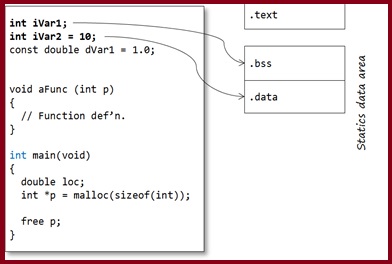
- one for uninitialized-definitions (int iVar1;).
- one for initialised-definitions (int iVar2 = 10;)
So it would not be unexpected for the address of iVar1 and iVar2 to not be adjacent to each other in memory.
The uninitialized-definitions’ section is commonly known as the .bss or ZI section. The initialised-definitions’ section is commonly known as the .data or RW section.
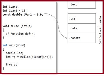
Constants may come in two forms:
- User-defined constant objects (for example const int c;)
- Literals (‘magic numbers’, macro definitions or strings)
The traditional C model places user-defined const objects in the .data section, along with non-const statics (so they may not be truly constant – this is why C disallows using constant integers to initialise arrays, for example)
Literals are commonly placed in the .text / .code section. Most compilers will optimise numeric literals away and use their values directly where possible.
Many modern C toolchains support a separate .const / .rodata section specifically for constant values. This section can be placed (in ROM) separate from the .data section. Strictly, this is a toolchain extension.
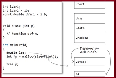
The majority of variables are defined within functions and classed as automatic variables. This also includes parameters and any temporary-returned-object (TRO) from a non-void function.
The default model in general programming is that the memory for these program objects is allocated from the stack. For parameters and TRO’s the memory is normally allocated by the calling function (by pushing values onto the stack), whereas for local objects, memory is allocated once the function is called. This key feature enables a function to call itself – recursion (though recursion is generally a bad idea in embedded programming as it may cause stack-overflow problems). In this model, automatic memory is reclaimed by popping the stack on function exit.
It is important to note that the compiler does NOT create a .stack segment. Instead, opcodes are generated that access memory relative to some register, the Stack Pointer, which is configured at program start-up to point to the top of the stack segment (see below)
However, on most modern microcontrollers, especially 32-bit RISC architectures, automatics are stored in scratch registers, where possible, rather than the stack. For example the ARM Architecture Procedure Call Standard (AAPCS) defines which CPU registers are used for function call arguments into, and results from, a function and local variables.
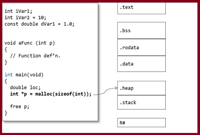
Memory for dynamic objects is allocated from a section known as the Heap. As with the Stack, the Heap is not allocated by the compiler at compile time but by the Linker at link-time.
The compiler produces relocatable object files – .o files.
The object file contains the compiled source code – opcodes and data sections. Note that the object file only contains the sections for static variables. At this stage, section locations are not fixed.
The .o file is not (yet) executable because, although some items are set in concrete (for example: instruction opcodes, pc-relative addresses, “immediate” constants, etc.), static and global addresses are known only as offsets from the starts of their relevant sections. Also, addresses defined in other modules are not known at all, except by name. The object file contains two tables – Imports and Exports:
- Exports contains any extern identifiers defined within this translation unit (so no statics!)
- Imports contains any identifiers declared (and used) within the translation; but not defined within it.
Note the identifier names are in name-mangled form.

3. Assembler:

In this stage the assembly code that is generated by the compiler gets converted into object code by the assembler.
- The input file for this stage is *.asm file.
- The output file is *.o or *.obj file.
- Note that compilers nowadays can generate an object code without the need of an independent assembler.
- The output of this stage is an object file that contains opcodes and data sections.
After the code generation is finished the compiler allocates memory for code and data in sections; each section has different information and is defined by name or attributes of information stored in them.

To be able to understand how the compiler allocates memory to the code and data, first we have to know the different memory segments and what they contain.
- Object file contains the sections for static variables; that are available during the whole program.
- Symbol table is used to store all variable names and their attributes.
- Debug info section that has the mapping between the original source code and the information needed by the debugger.
- Exports section contains global symbols either functions or variables.
- Imports section contains symbol names that are needed from other object files.
- Exports, imports, and symbol table sections are used by the linker during linking stage.
4. Linker:

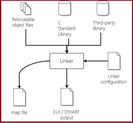
In this stage the different object files that are generated by the assembler gets converted into one relocatable file by the linker.

- The input file for this stage is *.o file, and c standard libraries.
- The output file is relocatable file.
- While combining the object files together, the linker performs the following operations:
- Symbol resolution.
- Relocation
Symbol resolution:
In multi-file program, if there are any references to labels defined in another file, the assembler marks these references as “unresolved”. When these files are passed to the linker, the linker determines the values of these references from other object files, and patches the code with the correct values. And if the linker didn’t find any references to these labels in any object file, it will throw and a linking error “unresolved reverence to variable”.
If the linker finds same symbol defined in two object files, it will report a “redefinition” error.
Relocation:
Relocation is the process of changing addresses already assigned to labels. This will also involve patching up all references to reflect the newly assigned address.
Primarily, relocation is performed for the following two reasons: Section Merging, and section placement.
Section Merging:
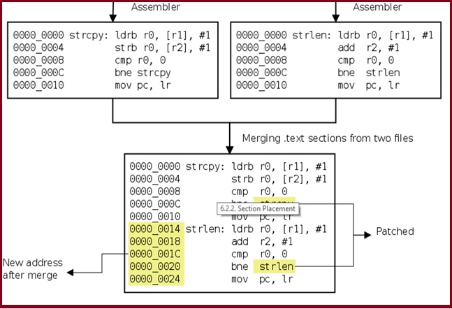
In each file, the linker is responsible for merging sections from the input files, into sections of the output file. By default, the sections, with the same name, from each file is placed contiguously and the label to references are patched to reflect the new address.
Section Placement:
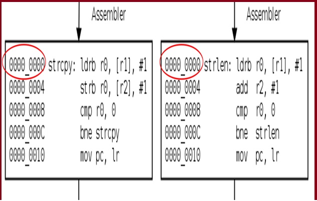

When a program is assembled each section is assumed to start from address 0. And thus, labels are assigned values relative to the start of the section. When the final executable is created, the section is placed at some address X. And all references to the labels defined within the section, are incremented by X, so that they point to the new location.
5. Locator:
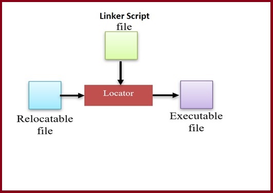
In this stage the process of assigning physical addresses to the relocatable file that is produced from the linker is performed using a locator.
- The input file for this stage relocatable file, and Linker script file.
- The output file is executable file.
- A locator is a tool that performs the conversion from relocatable program to executable binary image.
- The linker script file provides the locator with the required information about the actual memory layout and then the locator performs the conversion to produce a single executable binary file.
- Note that the locator can be found as a separate tool or with the linker.
Linker Script File:
Linker Script File or linker configuration file (LCF) is responsible to tell the locator how to map the executable into proper addresses.
- It controls the memory layout of the output file as it provides information about the memory on the target board as input to the locator.
- LCF defines physical memory layout (Flash/SRAM) and placement of the different program regions.
- LCF is highly compiler dependent, so each will have its own format.

The linker configuration file shown above leads to a fairly typical memory layout shown here
- .cstartup – the system boot code – is explicitly located at the start of Flash.
- .text and .rodata are located in Flash, since they need to be persistent
- .stack and .heap are located in RAM.
- .bss is located in RAM in this case but is (probably) empty at this point. It will be initialised to zero at start-up.
- The .data section is located in RAM (for run-time) but its initialisation section, .sdata, is in ROM.
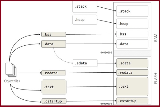
The Linker will perform checks to ensure that your code and data sections will fit into the designated regions of memory.
6.Loading:
ELF or DWARF are target-independent output file formats. In order to be loaded onto the target the ELF file must be converted into a native flash / PROM format (typically, .bin or .hex)
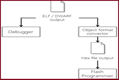
The final output of the C Build process will be an executable binary image of our source code that is ready to be loaded to our embedded target.
Key points-
- The compiler produces opcodes and data allocation from source code files to produce an object file.
- The compiler works on a single translation unit at a time.
- The linker concatenates object files and library files to create a program
- The linker is responsible for allocating stack and free store sections
- The linker operation is controlled by a configuration file, unique to the target system.
- Linked files must be translated to a target-dependent format for loading onto the target.

Leave a comment