
Turning on an LED with your Raspberry Pi’s GPIO Pins
One of the biggest selling points of the Raspberry Pi is its GPIO, or General Purpose Input/Output ports. They are the little pins sticking out of the circuit board and allow you to plug various devices into your Raspberry Pi. With a little programming, you can then control them or detect what they are doing.
In this tutorial I am going to show you how to light an LED. In addition to your Raspberry Pi running Raspbian, what you will need is:


- A Breadboard
- An LED
- A 330 ohm resistor
- Two Male-Female jumper wires
- power supply
The Breadboard
The breadboard is a way of connecting electronic components to each other without having to solder them together. They are often used to test a circuit design before creating a Printed Circuit Board (PCB).
The holes on the breadboard are connected in a pattern.

With the breadboard show in the above, the top row of holes are all connected together – marked with red dots. And so are the second row of holes – marked with blue dots. The same goes for the two rows of holes at the bottom of the breadboard.
In the middle, the columns of wires are connected together with a break in the middle. So, for example, all the green holes marked are connected together, but they are not connected to the yellow holes, nor the purple ones. Therefore, any wire you put into the green holes will be connected to other wires poked into the other green holes.
The LED
![]()
LED stands for Light Emitting Diode, and glows when electricity is passed through it.
When you pick up the LED, you will notice that one leg is longer than the other. The longer leg (known as the ‘anode’), is always connected to the positive supply of the circuit. The shorter leg (known as the ‘cathode’) is connected to the negative side of the power supply, known as ‘ground’.
LEDs will only work if power is supplied the correct way round (i.e. if the ‘polarity’ is correct). If you find that they do not light in your circuit, it may be because they have been connected the wrong way round.
The Resistor
![]()
You must ALWAYS use resistors to connect LEDs up to the GPIO pins of the Raspberry Pi. The Raspberry Pi can only supply a small current (about 60mA). The LEDs will want to draw more, and if allowed to they will burn out the Raspberry Pi. Therefore putting the resistors in the circuit will ensure that only this small current will flow and the Raspberry Pi will not be damaged.
Resistors are a way of limiting the amount of electricity going through a circuit; specifically, they limit the amount of ‘current’ that is allowed to flow. The measure of resistance is called the Ohm (Ω), and the larger the resistance, the more it limits the current. The value of a resistor is marked with coloured bands along the length of the resistor body.
You will be using a 330Ω resistor. You can identify the 330Ω resistors by the colour bands along the body. The colour coding will depend on how many bands are on the resistors supplied:
- If there are four colour bands, they will be Orange, Orange, Brown, and then Gold.
- If there are five bands, then the colours will be Orange, Orange, Black, Black, Brown.
It does not matter which way round you connect the resistors. Current flows in both ways through them.
Jumper Wires
Jumper wires are used on breadboards to ‘jump’ from one connection to another. The ones you will be using in this circuit have different connectors on each end. The end with the ‘pin’ will go into the Breadboard. The end with the piece of plastic with a hole in it will go onto the Raspberry Pi’s GPIO pins.

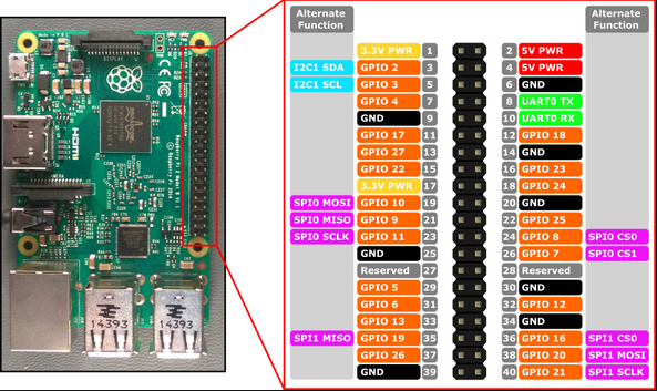
The Raspberry Pi’s GPIO Pins
GPIO stands for General Purpose Input Output. It is a way the Raspberry Pi can control and monitor the outside world by being connected to electronic circuits. The Raspberry Pi is able to control LEDs, turning them on or off, or motors, or many other things.
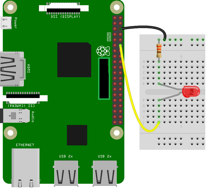
Connecting the Circuit
The LED has 2 legs. The longer leg, ‘anode’, is always connected to positive supply. The shorter leg,’cathode’, is always connected to ground.
You need a resistor is the circuit to limit the amount of current in the circuit. Without the resistor the current flowing through the LED will be much larger and lead to a short damaging the circuit.
You can identify a 330 Ohm resistor using the color coding on the resistor:
- If there are four colour bands, they will be Orange, Orange, Brown, and then Gold.
- If there are five bands, then the colours will be Orange, Orange, Black, Black, Brown.
Connect the circuit
- Use a jumper wire to connect the ground ( Pin 3) of GPIO to rail marked in blue on the breadboard.
- Connect the resistor from the same row on the breadboard to a column on the breadboard.
- Connect the LED with the cathode in the same row as the resistor. Insert the anode in the adjacent row.
- Use another jumper cable to connect the GPIO Pin 18 ( 3.3 V) in the same row as the anode of LED.
The Code
You are now ready to write some code to switch the LED on. Turn on your Raspberry Pi and open the terminal window.or Open a text editor like nano/vi using a terminal.
Create a new text file “LED.py” by typing the following:
nano LED.py
Type in the following code:
import RPi.GPIO as GPIO

import time

GPIO.setmode(GPIO.BCM)

GPIO.setwarnings(False)

GPIO.setup(18,GPIO.OUT)

print "LED on"

GPIO.output(18,GPIO.HIGH)

time.sleep(1)

print "LED off"

GPIO.output(18,GPIO.LOW)
Once you have typed all the code and checked it, save and exit the text editor with “Ctrl + x” then “y” then “enter”.
Running the Code
To run this code type:
sudo python LED.py
You will see the LED turn on for a second and then turn off.
Explanation
So, what is happening in the code? Let’s go through it a line at a time:
import RPi.GPIO as GPIO |
The first line tells the Python interpreter (the thing that runs the Python code) that it will be using a ‘library’ that will tell it how to work with the Raspberry Pi’s GPIO pins. A ‘library’ gives a programming language extra commands that can be used to do something different that it previously did not know how to do. This is like adding a new channel to your TV so you can watch something different. |
import time |
Imports the Time library so that we can pause the script later on. |
GPIO.setmode(GPIO.BCM) |
Each pin on the Raspberry Pi has several different names, so you need to tell the program which naming convention is to be used. |
GPIO.setwarnings(False) |
This tells Python not to print GPIO warning messages to the screen. |
GPIO.setup(18,GPIO.OUT) |
This line tells the Python interpreter that pin 18 is going to be used for outputting information, which means you are going to be able to turn the pin ‘on’ and ‘off’. |
print "LED on" |
This line prints some information to the terminal. |
GPIO.output(18,GPIO.HIGH) |
This turns the GPIO pin ‘on’. What this actually means is that the pin is made to provide power of 3.3volts. This is enough to turn the LED in our circuit on. |
time.sleep(1) |
Pauses the Python program for 1 second |
print "LED off" |
This line prints some information to the terminal. |
GPIO.output(18,GPIO.LOW) |
This turns the GPIO pin ‘off’, meaning that the pin is no longer supplying any power. |
And that’s it! You are now able to turn an LED on and off.

Leave a comment