
What is LoRa?
LoRa stands for Long Range. It is a wireless data communication technology based on spread spectrum modulation techniques derived from chirp spread spectrum (CSS) technology. It was first introduced by Cycleo in 2010, a company in Grenoble, France, and later acquired by Semtech.
The spread spectrum modulation technique provides secure communications by spreading the signal over a large frequency band and allows long-range communication with low bandwidth (which means low data rate) without consuming much power.
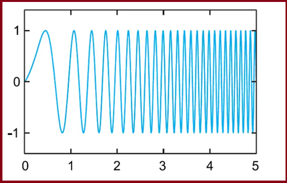
LoRa Chirp Spread Spectrum Modulation
Based on LoRa, the LoRaWAN (LoRa for Wide Area Networks) specification extended the LoRa physical communication layer into the Internet by adding a MAC layer. The LoRaWAN specification is a software layer that defines how devices must use the LoRa, for example, when they transmit or receive messages. The LoRaWAN specification is open-source; it has been supported and maintained by the LoRa Alliance since 2015.
Lora comes in different frequency ranges. It transmits over license-free megahertz radio frequency bands: There are the most common frequency bands are:

- 433 MHz (Asia)
- 868 MHz (Europe)
- 915 MHz (North America)
Also, note that every country has its unlicensed frequency range. anyone can freely use them without having to get a license. Please check the link for available unlicensed frequencies used in your country.
What is LoraWAN?
LoRaWAN is a Low Power, Wide Area (LPWA) networking protocol designed to wirelessly connect battery-operated ‘things’ to the internet in regional, national or global networks, and targets key Internet of Things (IoT) requirements such as bi-directional communication, end-to-end security, mobility and localization services.
LoRaWAN Network Architecture
A typical LoRaWAN network architecture includes the following essential parts: end-devices (usually sensors), a base station or gateway, also known as Long Range Relay (LRR), a network server also known as Long Range Controller (LRC), and the Operation Support System (OSS) for provisioning and management of the network.

Typical LoRaWAN® network architecture example. Image credits: The Things Network.
From the image above, notice there is a fundamental difference between a network server and a gateway. The network server controls the virtualized MAC layer of the LoRaWAN network while gateways are devices pre-integrated with the network server to ease the LPWAN rollout and provisioning. LoRaWAN network servers and gateways access can be public or private.

Lorawan Architecture
LoRaWAN networks are usually deployed in a star-of-stars topology; this means that gateways manage data between end-devices and a network server. Gateways are connected to the central network server via the Internet, while end-devices use LoRato send and receive data to and from the gateways; end-devices are not exclusively tied to a single gateway, end-devices broadcast information to all the gateways in range. Communication in LoRaWAN networks is natively bi-directional, although uplink communication between end-devices and the central network server is expected to be predominant in the network.
Star networks topologies provide the best relationship between long-range communications, the number of gateways or base stations in the network, end-devices power consumption, and battery life.

LoRa Topologies
Star networks present several advantages compared to other network topologies:
- Gateways can be added to the network anywhere and anytime without prior planning.
- Message delivery is more robust since multiple gateways receive the same data packets during each uplink.
Data Rates
Communication between end-devices and gateways in LoRaWAN networks is spread out on different frequency channelsand data rates (communications using different data rates do not interfere with each other).
LoRasupports data rates ranging from 300 bps to 5 kbps for a 125 kHz bandwidth.
To maximize the battery life of each end-device and the overall capacity available through the network, LoRaWAN uses an Adaptive Data Rate (ADR) mechanism for optimizing data rates, airtime, and power consumption. ADR controls the following transmission parameters on end-devices:
- Spreading factor: thespeed of data transmission. Lower spreading factors mean a higher data transmission rate.
- Bandwidth: theamount of data that can be transmitted from one point to another within the network.
- Transmission power: the energy that the end-device transmitter produces at its output.
The table below shows compares spreading factor, data rate, and time on-air at a bandwidth of 125 kHz (range is an indicative value, it will depend on the propagation conditions):
| Spreading Factor | Data Rate | Range | Time on-Air |
| SF7 | 5470 bps | 2 km | 56 ms |
| SF8 | 3125 bps | 4 km | 100 ms |
| SF9 | 1760 bps | 6 km | 200 ms |
| SF10 | 980 bps | 8 km | 370 ms |
| SF11 | 440 bps | 11 km | 40 ms |
| SF12 | 290 bps | 14 km | 1400 ms |
End-devices may transmit on any channel available at any time, using any available data rate, as long as the following rule is respected:
- The end-device changes channel in a pseudo-random fashion for every transmission. The resulting frequency diversity makes the system more robust against interference.
Also, local regulations must be respected, for example:
- In the EU868 band, the end-device must respect the maximum transmit duty cycle relative to the sub-band used and local regulations (1% for end-devices).
- In the US915 band, the end-device must respect the maximum transmit duration (or dwell time) relative to the sub-band used and local regulations (400ms).

LoRaWAN® network layers. Image credits: Semtech.
Regional Parameters
The LoRaWAN Regional Parameters specification is a companion to the LoRaWAN® network layer specification. While the LoRaWAN network layer specification defines the air interface between a compliant end-device (sensor, actuator, tracker, etc.) and a compliant network core, the LoRaWAN Regional Parameters specification defines the adaptation of the LoRaWAN network layer specification to comply with the various regulations enforced throughout the world on the use of various frequency bands of the unlicensed spectrum which are available.
Also, the LoRaWAN Regional Parameters specification documents the physical layer configurations required for the compliant operation of LoRaWAN Link Layer radios using various radio frequency modulation techniques.
The idea behind the LoRaWAN Regional Parameters specification is to create the smallest number of regional channel plans covering the largest possible number of regulatory regions. With this, complexity is decreased to implementers as well as the certification cost (end-device certification is enumerated by network layer, Regional Parameters and channel plan revision).
LoRaWAN Regional Parameters specifications do not specify everything. They only cover a region by specifying the common denominator. For example, the LoRaWAN Regional Parameters for Asia only specify a common subset of channels, but there are variations between regulations in Asian countries. Furthermore, each network server, for example TTN, is free to select additional parameters, such as additional emission channels.
Classes
The LoRaWAN specification has three different communication profiles between devices and applications: Class A, Class B, and Class C. Each class serves different application needs and has optimized requirements for specific purposes. The main difference between the three classes is latency and power consumption; end-devices can always send uplinks when needed, but its class will determine when to receive downlinks.
All LoRaWAN devices must implement Class A; Class B, and Class C are extensions of Class A profile.
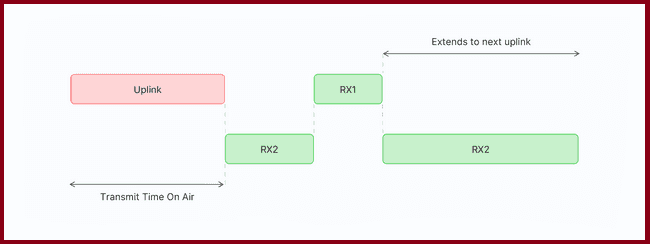
Class A: “Aloha”
Class A devices implement a bi-directional communication profile where two short downlinks follow the end-device uplink transmission receive windows, usually referred to as RX1 and RX2. If the server does not respond in either RX1 or RX2 windows, the next opportunity will be after the next uplink transmission. Class A devices are often battery-powered and spend most of the time in sleep mode; therefore, they have the lowest energy consumption, keep long intervals between uplinks, and have high downlink latency.

Class A default configuration profile. Image credits: The Things Network.
Class B: The “Beaconing” Class
Class B devices extend Class A devices by adding scheduled receive windows for downlinks, and, therefore, they emulate a continuously receiving device by opening receive windows at fixed time intervals. This class should be implemented when low latency of downlink communication while keeping the power consumption as low as possible is required.

Class B default configuration profile. Image credits: The Things Network.
Class C: Continuous Reception
Class C communication profile is used in applications with enough power available, so there is no need to minimize the time of the reception windows; this is the case of most actuators (e.g., smart plugs, street lights, electrical meters, etc.) Class C devices always listen for downlinks messages unless they transmit an uplink message. This behavior results in the lowest latency between the server and the end-device.
Class C default configuration profile. Image credits: The Things Network.
LoRa Range
LoRa could achieve a distance up to 3 miles (5 kilometers) in urban areas, and up to 10 miles (15 kilometers) or more in rural areas (line of sight).
LoRa Applications
LoRa is the de facto technology for IoT based on its widespread adoption and will be responsible for connecting IoT devices. LoRa is very flexible because of its long-range and low-power features which also makes it perfect for battery-operated sensors and low-power applications in various fields like:
- industrial IoT (IIoT)
- smart environment monitoring
- smart agriculture
- smart homes and cities
- smart utilities and metering
- smart supply chain and logistics
Please note that Lora is not suitable where needs high data-rate transmission capabilities and frequent transmissions.
Interfacing Lora sx1278 with Arduino Uno
In this part of the article, we will show you how to send and receive data between two Lora modules using Arduino IDE. We will use Arduino Uno as a microcontroller unit to interface with LoRa. To demonstrate the technology we will build a simple project that will control a led (ON or OFF) according to the LDR (Light Dependent Resistor) value wirelessly.
LoRa SX1278 (Ra-02) Module
Ra-02 wireless transmission module based on SEMTECH’s SX1278 wireless transceiver. It follows advanced LoRa spread spectrum technology, with a high communication distance of more than 10 kilometers and a frequency is 433MHz. It has the ability of anti-jamming and has the function of air wake-up Consumption. The SX1278 RF module is mainly used for long-range spread spectrum communication, and it can resist Minimizing current consumption. The SX1278 has a high sensitivity of -148 dBm with a power output of +20 dBm, a long transmission distance, and high reliability.

Figure: Ra-02 Module
Pinout of Lora Ra-02:

Figure: LoRa Ra-02 Module Pin Out
Antenna is one of the important components of LoRa modules. It is mandatory to use an antenna while operating the Lora modules otherwise the output transmitting power will damage the Module. I will use a 433MHz antenna for the Ra-02 module because it is rated 433MHz.
What is LDR?
LDR (Light Dependent Resistor) is a special type of resistor that works on the photoconductivity principle, which means that resistance changes according to light intensity. Its resistance decreases with an increase in the power of light. It is often used as a light sensor or used in areas where we need to have light sensitivity.

LDR (light-dependent resistor)
In this article, we use LDR as a light sensor to ON or OFF the LED light wirelessly. We connect LDR in the transmitter and LED in the receiver.
Circuit Connections
In this section of the article, We will show you how to connect LoRa (Ra-02) to Arduino Uno with the help of the connection diagram and pin description table. For demonstration purposes, we will build two circuits.
One is for the transmitter end and another is for the receiver end. At the transmitter end, we also connect an LDR sensor which detects the intensity of the light and sends the information to the receiver end wirelessly. On the receiver side, we also connect a LED to the Arduino. We just collect the LDR value from the transmitter side wirelessly and ON-OFF our LED accordingly.
we have powered the transmitter circuit with a 5 Volt Li-ion battery and powered the receiver circuit from a laptop USB port.
Arduino LoRa transmitter connection
In the transmitter side, I will connect LoRa (Ra-02) to Arduino Uno through SPI communication protocol. Because Ra-02 module supports SPI protocol. The connection is shown in the circuit below:
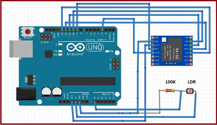
Arduino LoRa transmitter connection
I also connect an LDR sensor to the A0 pin of Arduino. We will read analog values (0 to 1024) from LDR(A0 pin). Then, send the value through LoRa wirelessly to our Receiver end.
The connection and pin description of Arduino and Lora are shown in the table below:

Transmitter Connection
Arduino LoRa receiver connection
Receiver side connection is same as trimester side. We just add a LED to pin D2 of Arduino. All other connections are the same. The circuit diagram is shown below:

Arduino LoRa receiver connection
The connection and pin description of Arduino and Lora are shown in the table below:

Figure: Arduino LoRa receiver connection
Preparing the Arduino IDE
After circuit connection, Our next step to prepare Arduino IDE. In this project we will use arduino-LoRa library by Sandeep Mistry. You can download the library from GitHub and add to your Arduino IDE or you can install the library from Arduino IDE.
To install, the library from Arduino IDE, Open your IDE and go to Sketch -> Include Library -> Manage Libraries and search for “LoRa Radio”. Then install the library called LoRa by Sandeep Mistry. After installation complete restart your Arddiuino IDE.

Install LoRa library
Arduino LoRa Transmitter Code
After Prepared the circuit and Arduino IDE copy the code to your Arduino IDE. Then build and upload the code to your Arduino microcontroller.
/*
Lora Transmitter
Author:Dharmendra Kumar Yadav

 */

#include <SPI.h>

#include <LoRa.h>

//define the pins used by the transceiver module

#define NSS 10

#define RST 9

#define DIO0 3

// LDR connect to Arduino Analog pin A0

#define LDR A0

intldr_value = 0;

void setup() {

  //Initialize the serial monitor

Serial.begin(9600);

while (!Serial);

  // take pin R0 as input

pinMode(LDR, INPUT);

Serial.println("LoRa Sender");

  //setup LoRa NSS, RST and DIO0 pins for transceiver module

LoRa.setPins(NSS, RST, DIO0);

  // select the frequency according to your module. most common frequencies are 433E6,866E6 and 915E6

if (!LoRa.begin(433E6)) {

Serial.println("Starting LoRa failed!");

while (1);

  }

  // Change sync word (0xF3) to match the receiver

  // This is a unique message id. The sync word use to assures that LoRa messages don't match to other LoRa transceivers

  // 0-0xFF range

LoRa.setSyncWord(0xF3);

Serial.println("LoRa Initializing OK!");

}

void loop() {

  // map the analog value (0-1024) to (0-055)

intldr_value = map(analogRead(LDR),0,1024,0,255);

Serial.print("Sending packet: ");

Serial.print("LDR value: ");

Serial.println(ldr_value);

  // send packet

LoRa.beginPacket();

LoRa.print(ldr_value);

LoRa.endPacket();

delay(2000);

}
Arduino LoRa Receiver Code
/*

 * LoRa Receiver

 * Author: Dharmendra Kumar Ysdav

 */

#include <SPI.h>

#include <LoRa.h>

//define the pins used by the transceiver module

#define NSS 10

#define RST 9

#define DIO0 3

// LED Pin

#define LED 2

String loraString = "";

intval = 0;

void setup() {

  //Initialize the serial monitor

Serial.begin(9600);

while (!Serial);

  // LED configure for output

pinMode(LED, OUTPUT);

Serial.println("LoRa Receiver");

   //setup LoRa NSS, RST and DIO0 pins for transceiver module

LoRa.setPins(NSS, RST, DIO0);

  // select the frequency according to your module most common frequencies are 433E6,866E6 and 915E6

if (!LoRa.begin(433E6)) {

Serial.println("Starting LoRa failed!");

while (1);

  }

  // Change sync word (0xF3) to match the receiver

  // This is a unique message id. The sync word use to assures tahtLoRa messages don't match to other LoRa transceivers

  // 0-0xFF range

LoRa.setSyncWord(0xF3);

Serial.println("LoRa Initializing OK!");

}

void loop() {

  // try to parse packet

intpacketSize = LoRa.parsePacket();

if (packetSize) {

    // received a packet

Serial.print("Received packet '");

    // read packet

while (LoRa.available()) {

      // read the message from lora transmitter

int data = LoRa.read();

      // creating a string of message

loraString += (char)data;

    }

    //convert the string to integer and store it to a integer variable

val = loraString.toInt();

loraString = ""; // empty the string

    // print RSSI of packet

Serial.print("' with RSSI ");

Serial.println(LoRa.packetRssi());

  }

Serial.println(val);

if(val> 100){

Serial.println("LED ON");

      // If LRD value is greater tham 100 LED will ON

digitalWrite(LED, HIGH);

    } else{

Serial.println("LED OFF");

      // If LRD value is less tham 100 LED will OFF

digitalWrite(LED, LOW);

    }

}
Result
When we decrease the intensity of light by putting our hand or something on the top of the LDR sensor, this causes an increase in the resistance of the LDR sensor and the analog pin produces a value accordingly. This value sends by the transmitter circuit to the receiver circuit wirelessly and LED turns ON. When we take away our hand, the resistance of the LDR sensor decreases and the LED should turns OFF according to the program we wrote.

Leave a comment