
Introduction
In this tutorial, we will learn about Arduino RGB led interfacing. The RGB led consists of three different led’s, from the name you can guess that these led’s are red, green and blue. We can obtain many other colors by mixing up these colors.
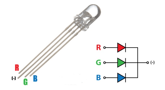
Since an RGB LED consists of three individual LEDs in a single package, the number of leads is different than that of a regular LED, which has two leads (one for cathode and the other for anode).
The through-hole variant of an RGB LED has 4 leads: one lead for each individual color (Red, Green and Blue) and the fourth one is the common lead (which can be either a cathode or anode).
Generally, the common cathode variant is found more frequently than the common anode variant. In this project, I will use a Common Cathode type RGB LED. I will show you how to drive both the variants.
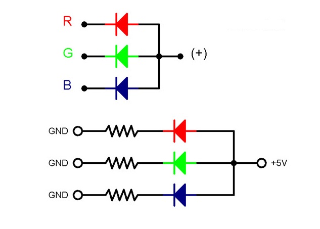
Common Anode type RGB LED-
The following image shows a Common Anode RGB LED along with its driving circuit.
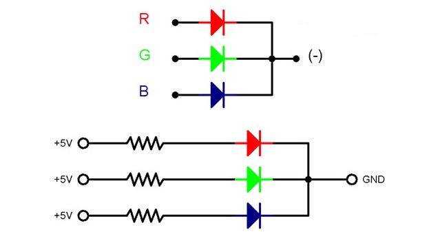
Common Cathode type RGB LED-
The following image shows a Common Cathode RGB LED along with its driving circuit.
Note:-You cannot distinguish between the common cathode and common anode type by just looking at the RGB led because both look same. You will have to make the connections to see that either it is common cathode or common anode.
The RGB led has one big lead than the other leads. In the common cathode case, it will be connected to GND and in the common anode case; it will be connected to 5V.
SMD RGB LED-
In through-hole RGB LED we have 4 leads. With the increasing popularity of SMD components, even RGB LEDs are being manufactured. below is the diagram of SMD RGB led.

An SMD RGB LED also contain three individual LEDs, each for Red, Green and Blue lights but each internal LED has its dedicated anode and cathode leads. Hence, the SMD variant has 6 leads.
Components
- Arduino UNO
- RGB LED
- 1KΩ Resistor x 3
- Mini Breadboard
- Connecting Wires
Interfacing RGB LED with Arduino
The Code
 /*
Display colors with RGB LED
Turns on an LED RED,GREEN and BLUE, repeatedly.
*/

// Pin 11,12,13 has an LED connected Through resistor.
// LED Anode is connected to +5V.
// give it a name:
int led = 13;
int led1 = 12;
int led2 = 11;
// the setup routine runs once when you press reset:
void setup() {
// initialize the digital pin as an output.
pinMode(led, OUTPUT); //define pin mode as output
pinMode(led1, OUTPUT); //define pin mode as output
pinMode(led2, OUTPUT); //define pin mode as output
}

void loop() {
digitalWrite(led2, HIGH); //making led pin high
digitalWrite(led1, HIGH);
digitalWrite(led, HIGH);
delay(500);
digitalWrite(led, LOW);
digitalWrite(led1, HIGH);
delay(500);
digitalWrite(led1, LOW);
digitalWrite(led2, HIGH);
delay(500);
digitalWrite(led2 , LOW);
delay(500);
}
Generate Colors using RGB LED?
we can generate a wide range of colors using an RGB LED just by varying the brightness of the individual R, G and B LEDs.
You might already have performed an experiment with dimming an LED using Arduino, where the brightness of LED is controlled either directly using the program or by interfacing a potentiometer.
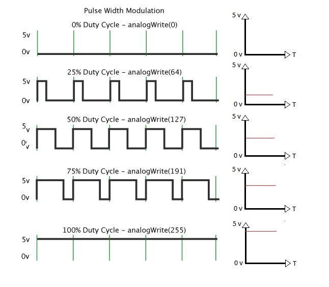
The technique used to control the brightness of an LED is called Pulse Width Modulation or simply PWM.
PWM is a technique where the amount of power delivered to a device can be controlled accurately and efficiently. PWM technique can be used to control the brightness of an LED, the speed of a motor or the direction of a servo motor.
There are two important factors to consider when dealing with PWM Technique: Duty Cycle and Frequency.
Duty cycle indicates the duration for which the pulse is HIGH over it period. It is measured in percentage and it indicates the voltage between OFF and ON levels (usually 0V and 5V).
Frequency of the pulse or the PWM Signal plays an important role as well and it must be sufficiently high than what the device feels its affect.
PWM With Ardiuno-
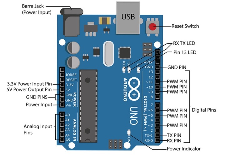
Arduino UNO has 6 Pins( as shown below) that can be used to generate PWM Signals: 3, 5, 6, 9, 10 and 11. In order to generate PWM signal of a specific duty cycle, you need to use the analogWrite(pin, value); function.Here, the value varies from 0 – 255 and corresponds to 0 – 100% Duty cycle.
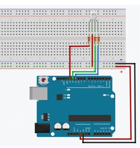
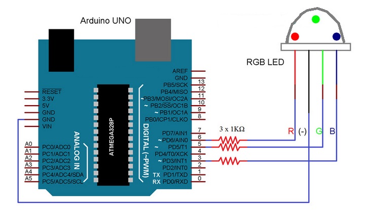
Circuit diagram-
PWM Pins 6, 5 and 3 are used in the project and they are connected to Red, green and Blue anode terminals of the RGB LED through individual current limiting resistors (1KΩ resistor are used but we can use 330Ω will bealso fine).
The code-
Interfacing of RGB LEDs with Arduino using PWM is given below.
const int redPin = 6;
const int greenPin = 5;
const int bluePin = 3;

void setup()
{
pinMode(redPin,OUTPUT);
pinMode(greenPin,OUTPUT);
pinMode(bluePin,OUTPUT);
}

void loop()
{
delay(1000);
primaryColors(1,0,0); // Red
delay(2000);
primaryColors(0,1,0); // Green
delay(2000);
primaryColors(0,0,1); // Blue
delay(2000);
primaryColors(1,1,0); // Yellow
delay(2000);
primaryColors(1,0,1); // Magenta
delay(2000);
primaryColors(0,1,1); // Cyan
delay(2000);
primaryColors(1,1,1); // White
delay(2000);

RGBFading();
}
void primaryColors(int redValue, int greenValue, int blueValue)
{
digitalWrite(redPin, redValue);
digitalWrite(greenPin, greenValue);
digitalWrite(bluePin, blueValue);
}

void RGBFading()
{
int x;
int redBrightness;
int greenBrightness;
int blueBrightness;

for (x = 0; x < 768; x++)
{
if (x <= 255)
{
redBrightness = 255 - x;
greenBrightness = x;
blueBrightness = 0;
}
else if (x <= 511)
{
redBrightness = 0;
greenBrightness = 255 - (x - 256);
blueBrightness = (x - 256);
}
else
{
redBrightness = (x - 512);
greenBrightness = 0;
blueBrightness = 255 - (x - 512);
}

analogWrite(redPin, redBrightness);
analogWrite(bluePin, blueBrightness);
analogWrite(greenPin, greenBrightness);

delay(10);
}
}
Working-
After making the connections as per the circuit diagram, copy the code and upload it to Arduino UNO. Initially, the RGB LED display individual colors Red, Green and Blue then followed by combination colors Yellow, Magenta and Cyan. White is also displayed.

Leave a comment