
Introduction
A Liquid Crystal Display commonly abbreviated as LCD is basically a display unit built using Liquid Crystal technology. When we build real life/real world electronics based projects, we need a medium/device to display output values and messages. The most basic form of electronic display available is 7 Segment display – which has its own limitations. The next best available option is Liquid Crystal Displays which comes in different size specifications. Out of all available LCD modules in market, the most commonly used one is 16×2 LCD Module which can display 32 ASCII characters in 2 lines (16 characters in 1 line). Other commonly used LCD displays are 20×4 Character LCD, Nokia 5110 LCD module, 128×64 Graphical LCD Display and 2.4 inch TFT Touch screen LCD display.
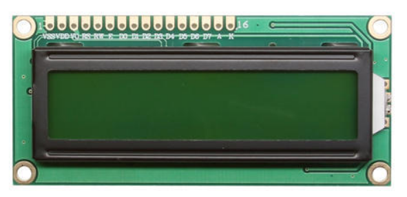
The Liquid Crystal Display modules play a very important role. Hence it is very important to learn about how to interface LCD with an Arduino of 16×2 in embedded system design.The 16×1 display unit has the 16 characters which present in one line and 16×2 display units have 32 characters which are present in the 2 line. We should know that to display the each character there are 5×10 pixels. Thus to display one character all the 50 pixels should be together. In the display,there is a controller which is HD44780 it is used to control the pixels of characters to display.
16×2 LCD Module Pin Out Diagram
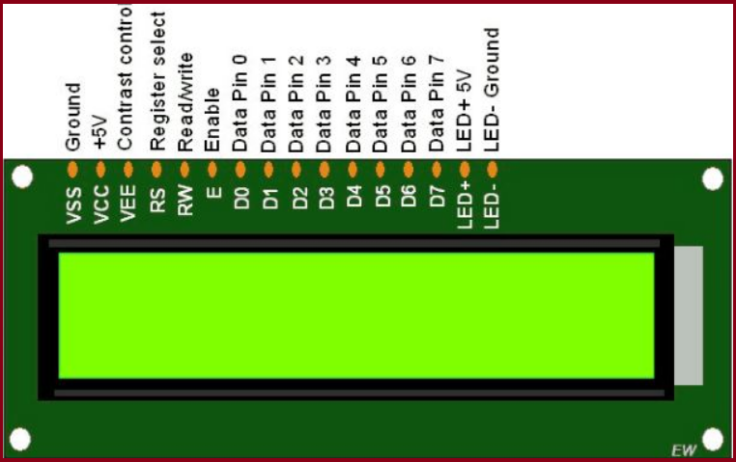
Pin diagram and description of each pin have explained in the following table.
| Pin No | Pin Name | Pin Description |
| Pin 1 | GND | This pin is a ground pin and the LCD is connected to the Ground |
| Pin 2 | VCC | The VCC pin is used to supply the power to the LCD |
| Pin 3 | VEE | This pin is used for adjusting the contrast of the LCD by connecting the variable resistor in between the VCC & Ground. |
| Pin 4 | RS | The RS is known as register select and it selects the Command/Data register. To select the command register the RS should be equal to zero. To select the Data register the RS should be equal to one. |
| Pin 5 | R/W | This pin is used to select the operations of Read/Write. To perform the write operations the R/W should be equal to zero. To perform the read operations the R/W should be equal to one. |
| Pin 6 | EN | This is a enable signal pin if the positive pulses are passing through a pin, then the pin function as a read/write pin. |
| Pin 7 | DB0 to DB7 | The pin 7 contains total 8 pins which are used as a Data pin of LCD. |
| Pin 15 | LED + | This pin is connected to VCC and it is used for the pin 16 to set up the glow of backlight of LCD. |
| Pin 16 | LED – | This pin is connected to Ground and it is used for the pin 15 to set up the glow of backlight of the LCD. |
LCD Interfacing with the Arduino Module
The following circuit diagram shows the liquid crystal display with the Arduino module. From the circuit diagram, we can observe that the RS pin of the LCD is connected to the pin 12 of the Arduino. The LCD of R/W pin is connected to the ground. The pin 11 of the Arduino is connected to the enable signal pin of LCD module. The LCD module & Arduino module are interfaced with the 4-bit mode in this project. Hence there are four input lines which are DB4 to DB7 of the LCD. This process very simple, it requires fewer connection cables and also we can utilize the most potential of the LCD module.
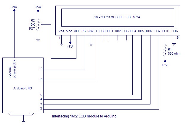
The digital input lines (DB4-DB7) are interfaced with the Arduino pins from 5-2. To adjust the contrast of the display here we are using a 10K potentiometer. The current through the back LED light is from the 560-ohm resistor. The external power jack is provided by the board to the Arduino. Using the PC through the USB port the Arduino can power. Some parts of the circuit can require the +5V power supply it is taken from the 5V source on the Arduino board.
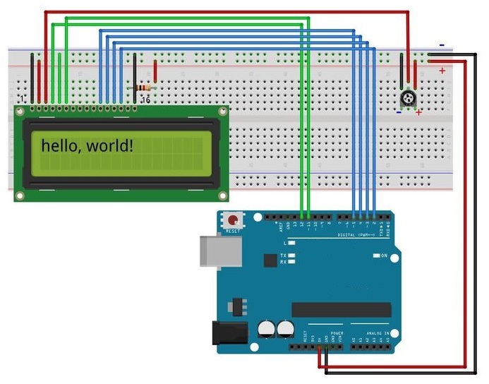
Circuit diagram-
The code-
/*
Author-Dharmendra Kumar yadav
The circuit:
* LCD RS pin to digital pin 12
* LCD Enable pin to digital pin 11
* LCD D4 pin to digital pin 5
* LCD D5 pin to digital pin 4
* LCD D6 pin to digital pin 3
* LCD D7 pin to digital pin 2
* LCD R/W pin to ground
* 10K resistor:
* ends to +5V and ground
* wiper to LCD VO pin (pin 3)

*/

// include the library code:
#include <LiquidCrystal.h>

// initialize the library by associating any needed LCD interface pin
// with the arduino pin number it is connected to
const int rs = 12, en = 11, d4 = 5, d5 = 4, d6 = 3, d7 = 2;
LiquidCrystal lcd(rs, en, d4, d5, d6, d7);

void setup() {
// set up the LCD's number of columns and rows:
lcd.begin(16, 2);
// Print a message to the LCD.
lcd.print("hello, world!");
}

void loop() {
// Turn off the display:
lcd.noDisplay();
delay(500);
// Turn on the display:
lcd.display();
delay(500);
}
About the program.
To facilitate communication between Arduino and LCD module, we make use of a built in library in Arduino <LiquidCrystal.h> – which is written for LCD modules making use of the Hitachi HD44780 chipset (or a compatible chipset). This library can handle both 4 bit mode and 8 bit mode wiring of LCD.
link for document – Liquid Crystal Library – before you continue down!
Library “LiquidCrystal.h” is used for easily controlling the LCD module using Arduino board with the help of built in methods defined inside the library For example, data string can be printed on the LCD module by merely calling a method lcd.print(). If you want to print “Hello World” at row 1, starting from column 3; first set the cursor at the desired position using method lcd.setCursor(1,3) and then write the command to print the characters as lcd.print(“Hello World”); . The library is readily available with the Arduino IDE (as its a pre installed standard library). The LiquidCrystal.h library provides functions/methods for almost all applications like printing a string, setting the cursor, initializing the LCD, scrolling the display, auto scroll, clear LCD, blink cursor etc.
Functions Used in Program
LiquidCrystal lcd() – is a constructor used to declare a variable of its type. Here ‘lcd’ is the variable declared using the constructor and is used to invoke methods defined inside the library LiquidCrystal.h (Example – lcd.print(); lcd.setCursor() and other methods)
lcd.begin() – is called to initialize the lcd screen and to pass the dimension of lcd screen (columns, rows) as parameters of the invoked method.
lcd.setCursor(col,row)
- This function positions the cursor of the LCD to a location specified by the row and column parameters.
- col is the column number at which the cursor should be at (0 for column 1, 4 for column 5 and so on).
- row is the row number at which the cursor should be at (0 for row 1, 1 for row 2).
- Example, for setting the cursor at the 5th column in the 2nd row, lcd.setCursor(4,1). lcd is the name of the object of the class LiquidCrystal.
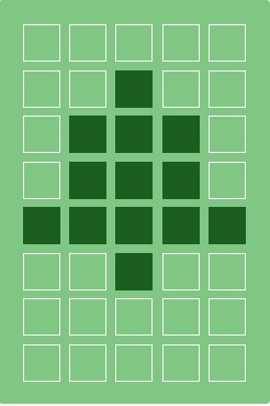
lcd.createChar(num,data)
- This function is used to create a new custom character for use on the LCD.
- num is the CGRAM location (0 to 7) at which the custom character is to be stored.
- data is array of eight bytes which represent the custom character.
- Custom character can be of 5×8 pixels only.
- Each custom character is specified by an array of eight bytes, one for each row. The five least significant bits of each byte determine the pixels in that row.
- To display a custom character on the screen, write() function needs to be used. CGRAM location number (0 to 7) of the custom character which is to be displayed on LCD is passed as an argument to the write function.
- Note : When referencing custom character “0”, you need to cast it as a byte, otherwise the compiler throws an error.
Program for scrolling the LCD screen using Arduino.
A simple program for scrolling a text message on the LCD screen using arduino is shown here. This is done using the “scroll()” method defined inside LiquidCrystal.h library. For example the method “lcd.scrollDisplayRight()” will scroll the display to right and the method”lcd.scrollDisplayLeft()” will scroll the display to left.
/*
Author-Dharmendra Kumar yadav
The circuit:
* LCD RS pin to digital pin 12
* LCD Enable pin to digital pin 11
* LCD D4 pin to digital pin 5
* LCD D5 pin to digital pin 4
* LCD D6 pin to digital pin 3
* LCD D7 pin to digital pin 2
* LCD R/W pin to ground
* 10K resistor:
* ends to +5V and ground
* wiper to LCD VO pin (pin 3)

*/
#include <LiquidCrystal.h>
int pos=0; // variable to hold cursor position

LiquidCrystal lcd(12, 11, 5, 4, 3, 2);

void setup()
{
 lcd.begin(16, 2);                              //initializes 16x2 LCD
 lcd.print("16x2 LCD MODULE & ARDUINO-UNO");   //text to display
}

void loop()
{
  for(pos=0; pos<2; pos++)
  {
lcd.scrollDisplayLeft();    //scrolls display left by two positions
  }
  delay(800);              //sets the speed at which display moves
}
Custom character create in Arduino-
we can Create a custom character for use on the LCD. Up to eight characters of 5×8 pixels are supported (numbered 0 to 7). The appearance of each custom character is specified by an array of eight bytes, one for each row. The five least significant bits of each byte determine the pixels in that row. To display a custom character on the screen, write() its number.
we can also create the custom charcter from here – custom charcter for LCD
code-
/* Author-Dharmendra Kumar yadav The circuit: * LCD RS pin to digital pin 12 * LCD Enable pin to digital pin 11 * LCD D4 pin to digital pin 5 * LCD D5 pin to digital pin 4 * LCD D6 pin to digital pin 3 * LCD D7 pin to digital pin 2 * LCD R/W pin to ground * 10K resistor: * ends to +5V and ground * wiper to LCD VO pin (pin 3)#include <LiquidCrystal.h> LiquidCrystal lcd(12, 11, 5, 4, 3, 2); // RS, E, D4, D5, D6, D7 byte customChar[] = { 0x00, 0x04, 0x0E, 0x0E, 0x1F, 0x04, 0x00, 0x00 }; void setup() { lcd.begin(16, 2); lcd.createChar(0, customChar); lcd.home(); lcd.write(0); } void loop() { }

Leave a comment