
Introduction-
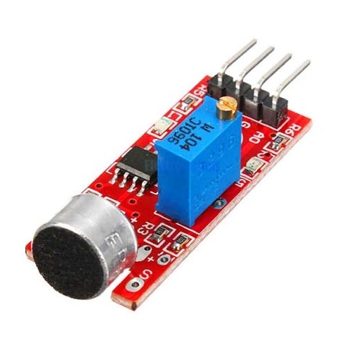
The Sound Sensor is a small board that combines a microphone and some processing circuitry.
These sound sensors are inexpensive, easy to interface with and are able to detect sounds of voice, claps or door knocks or any other sounds loud enough to picked up by the microphone.You can use them for a variety of sound reactive projects, for example, making your lights clap-activated or keeping an “ear” on your pets while you’re away.
Hardware Description-
The sound sensor is a small board that combines a microphone (50Hz-10kHz) and some processing circuitry to convert sound waves into electrical signals.
This electrical signal is fed to on-board LM393 High Precision Comparator to digitize it and is made available at OUT pin.
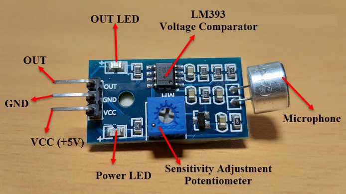
The module has a built-in potentiometer for sensitivity adjustment of the OUT signal.
You can set a threshold by using a potentiometer; So that when the amplitude of the sound exceeds the threshold value, the module will output LOW otherwise HIGH.
This setup is very useful when you want to trigger an action when certain threshold is reached. For example, when the amplitude of the sound crosses a threshold (when a knock is detected), you can activate a light or relay.
Sound Sensor Pin out-
The sound sensor only has four pins:
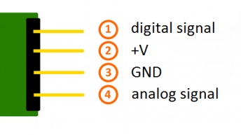
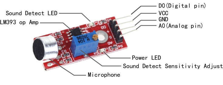
VCC -pin supplies power for the sensor. It is recommended to power the sensor with between 3.3V – 5V.
GND is a ground connection.
DO– pin outputs HIGH when conditions are quiet and goes LOW when sound is detected. You can connect it to any digital pin on an Arduino or directly to a 5V relay or similar device.
AO-pin outputs give analog value instead of the Digital value you can connect on analog pin of Ardiuno.
Material Required-
- Arduino
- Sound Sensor
- LED
- 220 ohm Resistors
- Mini Breadboard
- Connecting Wires
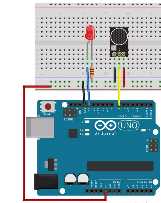
Circuit & Connections-
Connections are fairly simple. Start by connecting VCC pin on the module to 5V on the Arduino and GND pin to ground.
Now connect the DO pin to the digital pin 7 on your Arduino. That’s it!
Calibrating Sound Sensor-
To get accurate readings out of your sound sensor, it is recommended that you first calibrate it.
The module has a built-in potentiometer for calibrating the digital output (OUT).By turning the knob of the potentiometer, you can set a threshold. So that when the sound level exceeds the threshold value, the Status LED will light up and the digital output (OUT) will output LOW.
Now to calibrate the sensor, start clapping near the microphone and adjust the potentiometer until you see the Status LED on the module blink in response to your claps.
Code for Digital output-
/*
Author:-Dharmendra kumar yadav
*/
int ledPin=13;
int sensorPin=7;
boolean val =0;

void setup(){
  pinMode(ledPin, OUTPUT);
  pinMode(sensorPin, INPUT);
  Serial.begin (9600);
}

void loop (){
  val =digitalRead(sensorPin);
  Serial.println (val);
  // when the sensor detects a signal above the threshold value, LED flashes
  if (val==HIGH) {
    digitalWrite(ledPin, HIGH);
  }
  else {
    digitalWrite(ledPin, LOW);
  }
}
After making the connections and uploading the code to Arduino, snap or clap in front of the sensor. You can observe the LED connected to OUT Pin of the sound sensor as well as the Digital Pin 12 of Arduino will be active whenever it detects any sound.
code for Analog Reading-
/*
Author:-Dharmendra kumar yadav
*/
int Analog_Pin = A0;
void setup ()
{
pinMode(Analog_Pin, INPUT);
Serial.begin (9600);
}
void loop ()
{
float Analog;
Analog = analogRead (Analog_Pin);
Serial.print("Analog voltage :");
Serial.print(Analog, 4);
Serial.print("V, ");
Serial.print("Limit :");
}
Applications-
Sound Sensor can be used in various applications like:
- Security Systems
- Burglar Alarms
- Device Control
- Door Alarms

Leave a comment