
What is electronics switch? – A switch is an electrical component that can break an electrical circuit, interrupting the current or diverting it from one conductor to another. There are two main state of switch “open” and “close”. And each switch has a mechanism that is “toggle” or “momentary”. Toggle mean flip switch for continuous “on” or “off”. Momentary mean push-for “on” or push-for “off”.
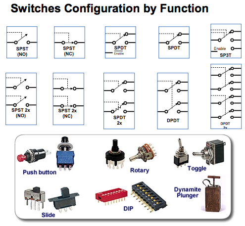
Based on the number of poles and throws, switches are classified into following types. The pole represents the number of individual power circuits that can be switched. Most of the switches are designed have one, two or three poles and are designated as single pole, double pole and triple pole.
The number of throws represents the number of states to which current can pass through the switch. Most of the switches are designed to have either one or two throws which are designated as single throw and double throw switches.
Single Pole Single Throw Switch (SPST)
 This is the basic ON and OFF switch consisting of one input contact and one output contact.
- It switches a single circuit and it can either make (ON) or break (OFF) the load.
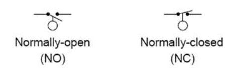
- The contacts of SPST can be either normally open or normally closed configurations .
Single Pole Double Throw Switch (SPDT)
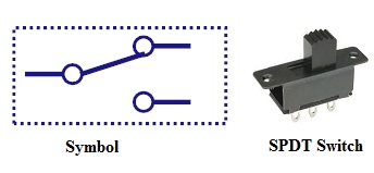 This switch has three terminals,one is input contact and remaining two are output contacts.
- This means it consist two ON positions and one OFF position.
- In most of the circuits, these switches are used as changeover to connect the input between two choices of outputs.
- The contact which is connected to the input by default is referred as normally closed contact and contact which will be connected during ON operation is a normally open contact.
Double Pole Single Throw Switch (DPST)
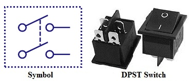
- This switch consists of four terminals,two input contacts and two output contacts.
- It behaves like a two separate SPST configurations, operating at the same time.
- It has only one ON position, but it can actuate the two contacts simultaneously, such that each input contact will be connected to its corresponding output contact.
- In OFF position both switches are at open state.
- This type of switches is used for controlling two different circuits at a time.
- Also, the contacts of this switch may be either normally open or normally closed configurations.
Double Pole Double Throw Switch (DPDT)
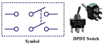
 This is a dual ON/OFF switch consisting of two ON positions.
- It has six terminals,two are input contacts and remaining four are the output contacts.
- It behaves like a two separate SPDT configuration, operating at the same time.
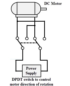
- Two input contacts are connected to the one set of output contacts in one position and in another position, input contacts are connected to the other set of output contacts.
Push Button Switch
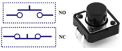 It is a momentary contact switch that makes or breaks connection as long as pressure is applied (or when the button is pushed).
- Generally, this pressure is supplied by a button pressed by someone’s finger.
- This button returns its normal position, once the pressure is removed.
- The internal spring mechanism operates these two states (pressed and released) of a push button.
- It consists of stationary and movable contacts, of which stationary contacts are connected in series with the circuit to be switched while movable contacts are attached with a push button.
- Push buttons are majorly classified into normally open, normally closed and double acting push buttons as shown in the above figure.
- Double acting push buttons are generally used for controlling two electrical circuits.
Toggle Switch
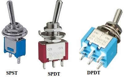 A toggle switch is manually actuated (or pushed up or down) by a mechanical handle, lever or rocking mechanism. These are commonly used as light control switches.
- Most of these switches come with two or more lever positions which are in the versions of SPDT, SPST, DPST and DPDT switch. These are used for switching high currents (as high as 10 A) and can also be used for switching small currents.
- These are available in different ratings, sizes and styles and are used for different type of applications. The ON condition can be any of their level positions, however, by convention the downward is the closed or ON position.
Limit Switch
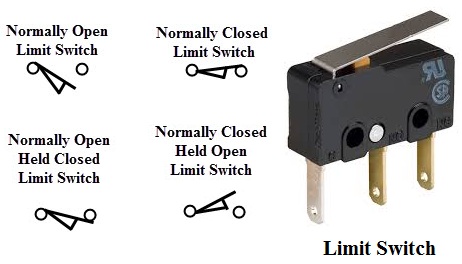 The control schemes of a limit switch are shown in above figure , in which four varieties of limit switches are presented.
- Some switches are operated by the presence of an object or by the absence of objects or by the motion of machine instead of human hand operation. These switches are called as limit switches.
- These switches consist of a bumper type of arm actuated by an object. When this bumper arm is actuated, it causes the switch contacts to change position.
Float Switches
- Float switches are mainly used for controlling DC and AC motor pumps according to the liquid or water in a tank or sump.
- This switch is operated when the float (or floating object) moves downward or upward based on water level in a tank.
- This float movement of rod or chain assembly and counterweight causes to open or close electrical contacts. Another form of float switch is the mercury bulb type switch that does not consist of any float rod or chain arrangement.
- This bulb consist of mercury contacts such that when the liquid level rises or falls, the state of contacts also changes.
- The ball float switch symbol is shown in the above figure. These float switches can be normally open or normally closed type.
Flow Switches
- These are mainly used to detect the movement of liquid or air flow through a pipe or duct. The air flow switch (or a micro switch) is constructed by a snap-action.
- This micro switch is attached to a metal arm .To this metal arm, a thin plastic or metal piece is connected.
- When a large amount of air passes through the metal or plastic piece, it causes the movement of metal arm and thus operates the contacts of the switch.
- Liquid flow switches are designed with a paddle that inserted across the flow of liquid in a pipe. When liquid flows through the pipe, force exerted against the paddle changes the position of the contacts.
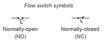
- The above figure shows the switch symbol used for both air flow and liquid flow. The flag symbol on the switch indicates the paddle which senses the flow or movement of liquid.
- These switches again normally open or normally closed type configurations.
Pressure Switches
- These switches are commonly used in industrial applications in order to sense the pressure of hydraulic systems and pneumatic devices.
- Depends on the range of pressure to be measured, these pressure switches are classified into diaphragm operated pressure switch, metal bellow type pressure switch and piston type pressure switch.
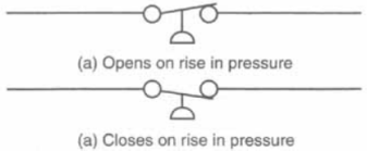
- In all these types, pressure detection element operates a set of contacts (which can be either double pole or single pole contacts).
- This switch symbol consist a half-circle connected to a line in which flat part indicates a diaphragm. These switches may be either normally open or normally closed type configurations.
Temperature Switches
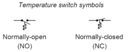
- The most common heat sensing element is the bimetallic strip that operates on the principle of thermal expansion.
- The bimetallic strips are made with two dissimilar metals (that are having different thermal expansion rates) and are bonded with each other.
- The switch contacts are operated when the temperature causes the strip to bend or wrap. Another method of operating the temperature switch is to use mercury glass tube.
- When the bulb is heated, mercury in the tube will expand and then generates pressure to operate the contacts.
Joystick Switch
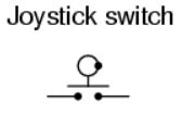
- Joystick switches are manually actuated control devices used mainly in portable control equipments.
- It consists of a lever which moves freely in more than one axis of motion.
- Depending on the movement of the lever pushed, one or more switch contacts are actuated.
- These are ideally suited for lowering, raising and triggering movements to the left and right.
- These are used for building machinery, cable controls and cranes. The symbol for the joystick is shown below.
Rotary Switches
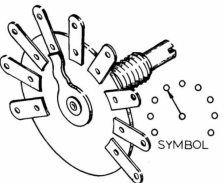
- These are used for connecting one line to one of many lines.
- Examples of these switches are range selectors in electrical metering equipment, channel selectors in communication devices and band selectors in multi-band radios.
- It consists of one or more moving contacts (knob) and more than one stationary contact.
- These switches are come with different arrangement of contacts such as single pole 12-way, 3-pole 4-way, 2-pole 6-way and 4-pole 3-way.
Electronic Switches
The electronic switches are generally called as solid state switches because there are no physical moving parts and hence absence of physical contacts. Most of the appliances are controlled by semiconductor switches such as motor drives and HVAC equipments.
There are different types of solid state switches are available in today market with different sizes and ratings. Some of these solid state switches include transistors, SCRs, MOSFETs, TRIACs and IGBTs.
Bipolar Transistors
A transistor either allows the current to pass or it blocks the current as similar to working of normal switch.
In switching circuits, transistor operates in cut-off mode for OFF or current blocking condition and in saturation mode for ON condition. The active region of the transistor is not used for switching applications.
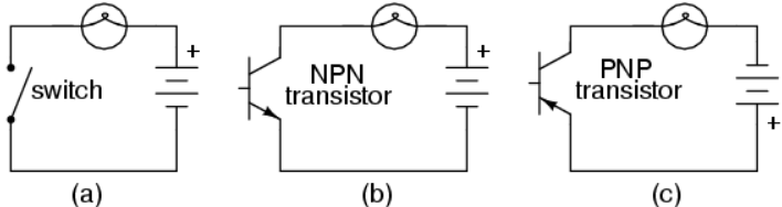
Both NPN and PNP transistors are operated or switched ON when a sufficient base current is supplied to it. When a small current flows though the base terminal supplied by a driving circuit (connected between the base and emitter), it causes to turns ON the collector-emitter path.
And it is turned OFF when the base current is removed and base voltage is reduced to a slight negative value. Even though it utilizes small base current, it is capable to carry much higher currents through the collector- emitter path.
Power Diode
A diode can perform switching operations between its high and low state impedance states. Semiconductor materials like silicon and germanium are used for constructing the diodes.
Usually, power diodes are constructed using silicon in order to operate the device at higher currents and higher junction temperatures. These are constructed by joining p and n type semiconductor materials together to form PN junction. It has two terminals namely anode and cathode.
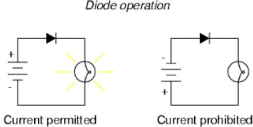
When the anode is made positive with respect to cathode and by the application of voltage greater than the threshold level, PN junction is forward biased and starts conducting (like ON switch). When the cathode terminal is made positive with respect to anode, PN junction reverse biased and its blocks the current flow (like OFF switch).
MOSFET
Metal Oxide Semiconductor Field Effect Transistor (MOSFET) is a unipolar and high frequency switching device. It is a most commonly used switching device is power electronic applications. It has three terminals namely drain (output), source (common) and gate (input).
It is a voltage controlled device, i.e., by controlling input (gate to source) voltage, resistance between the drain and source is controlled which further determines the ON and OFF state of the device.
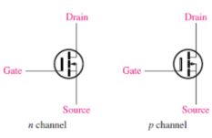
MOSFETs can be a P-channel or N-channel devices. The N-channel MOSFET is tuned ON by applying a positive VGS with respect to the source (provided that VGS should be greater than threshold voltage).
P-channel MOSFET operates in a similar manner of N-channel MOSFET but it uses reverse polarity of voltages. Both VGS and VDD are negative with respect the source to switch ON the P- channel MOSFET.
IGBT
IGBT (Insulated Gate Bipolar Transistor) combines the several advantages of bipolar junction power transistor and power MOSFET. Like a MOSFET, it is a voltage controlled device and has lower ON state voltage drop (less than that of MOSFET and closer to power transistor).
It is a three terminal semiconductor high speed switching device. These terminals are emitter, collector and gate.
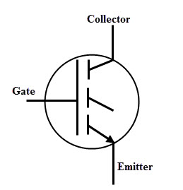
Similar to the MOSFET, IGBT can be turned ON by applying a positive voltage (greater than the threshold voltage) between the gate and emitter. IGBT can be turned by reducing the voltage across the gate-emitter to zero. In most of the case it needs negative voltage to reduce turn OFF losses and safely turn OFF the IGBT.
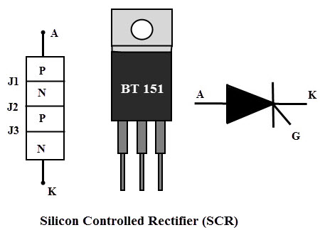
SCR
A Silicon Controlled Rectifier (SCR) most widely used high speed switching device for power control applications. It is a unidirectional device as a diode, consisting of three terminals, namely anode, cathode and gate.
An SCR is turned ON and OFF by controlling its gate input and biasing conditions of the anode and cathode terminals. SCR consists of four layers of alternate P and N layers such that boundaries of each layer forms junctions J1, J2 and J3.
TRIAC
Triac (or TRIode AC) switch is a bidirectional switching device which is an equivalent circuit of two back to back SCRs connection with one gate terminal.
Its capability to control AC power in both positive and negative peaks of the voltage waveform often makes these devices to be used in motor speed controllers, light dimmers, pressure control systems, motor drives and other AC control equipments.

DIAC
A DIAC (or DIode AC switch) is bidirectional switching device and it consists of two terminals which are not named as anode and cathode. It means that a DIAC can be operated in either direction regardless of the terminal identification. This indicates that the DIAC can be used in either direction.

When a voltage is applied across a DIAC, it either operates in forward blocking or reverse blocking mode unless the applied voltage is less than the breakover voltage. Once the voltage is increased more than breakover voltage, avalanche breakover occurs and device starts conducting.
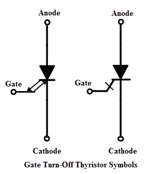
Gate Turn-Off Thyristor
A GTO (Gate Turn off Thyristor) is a bipolar semiconductor switching device. It has three terminals as anode, cathode and gate. As the name implies, this switching device is capable to turn OFF through gate terminal.
A GTO is turned ON by applying a small positive gate current triggers the conduction mode and turned OFF by a negative pulse to the gate. GTO symbol consists of double arrows on the gate terminal which represents the bidirectional flow of current through gate terminal.
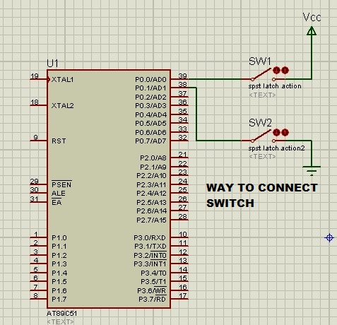
Circuit Diagram
Code
#include<reg51.h>
sbit switch1=P1^0;  // pin P1.0 IS accessed as  a variable name switch1
sfr led=0xa0;       // port P2 IS accessed as a variable name led
void main()
   {
switch1=0;  // make pin P1.0 as INPUT MODE
    while(1)
      {
       if(switch1==1)        //check switch is pressed or not
       led=0xff;     // led on
       else
       led=0x00;    // led off
      }
}

Leave a comment